Samuel
PFDs, known as process flow diagrams, detail the processes or relationships between the major components in a system from piping to instrumentation. They offer high level guidance on the sequence of processes required in an industrial application. In this article, we will discuss the purpose and process for generating a PFD, how to read a PFD, and the use of a PFD for the generation of other engineering drawings.

PFD Purpose and Process
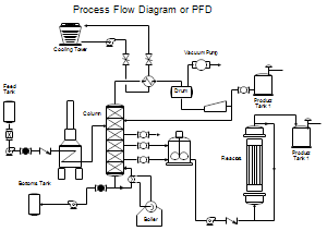
A process flow diagram (PFD) gives a high level overview of a system process at a plant or other facility. PFDs are typically the starting point in engineering a system as it outlines the chemical and physical processes a system must undergo before physical and mechanical components of the system are decided. Thus, PFDs should be considered instructive of what must happen within a system before considering how it will be done. PFDs serve as the base document in P&ID creation, which in turn informs general arrangement drawings and equipment production. A mass-flow balance of system inputs and outputs that ensure the process makes logic system is typically is generated alongside the PFD.

Generating a PFD starts with identifying the process a system must undergo, including the inputs, outputs, and any intermediate processes. Once the brainstorming portion of a PFD is complete, an engineer performs a mass flow balance, identifies the appropriate equipment, and begins the compilation of the PFD. Typically, PFDs are created using a multitude of different software including AutoCAD, Lucid Chart, Visme, Smart Draw, and Draw.io. PFDs may also be hand-drawn as long as the intended design may be clearly communicated with fabricators, engineers, technicians, and anyone involved in the creation of the system. Once the PFD has been created, it should be quality checked for accuracy and to ensure the design has been optimized. Typically for larger applications such as industrial plants, a larger team would collaborate in creating the PFD whereas small scale systems may require only a single engineer. In addition to informing other engineering documents, PFDs may also be used after the equipment is completed. Common use cases for the PFD in this scenario are training and analysis of potential system optimization.
Reading a PFD
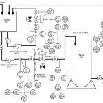
Reading a PFD requires knowledge of commonly used symbols and notations. A lot of the symbols and notations may be standardized depending on the application, for example, the International Organization for Standardization (ISO) or American National Standards Institute (ANSI) has specified standards that may apply. This section outlines some of the main symbols and notations used for PFDs.
Piping

Pipes transport liquids, gases, and other fluids while connecting the major components of a system. Construction details of a piping system typically do not show up on a PFD and are expressed generally on a P&ID and with greater detail on a pipe spool drawing.
Vessels

Vessels are usually classified in two ways: atmospheric tanks that do not hold pressure or pressure vessels. Vessel size is not called out on a PFD, but typically is known at least in general terms during this phase of development.
Heat Exchangers

Heat exchangers are crucial in many thermodynamic systems and allow for a system to transfer heat across different portions of the system in an efficient manner. The specific type of heat exchanger is a function of the heating required, discharge heat available, physically available space, and the subject process media.
Pumps

Pumps are used in many systems to control pressure by compressing then expelling the fluid. At this stage in development, physical pump placement and atmospheric head are typically not considered.
Instruments

Instrumentation is vital in controlling, monitoring, and maintaining various aspects of a system. It allows for technicians and engineers to have control over the processes of a system and aids in general maintenance as well. Some PFDs may show instrumentation, but often this level of detail is left for the P&ID.
Valves

Valves are crucial in regulating flow within a system by either closing, throttling, or completely opening flow at a specific point in a system.
Applications
PFDs are the general foundation and starting point in the construction and engineering of a system. Many other engineering documents are created with the PFD serving as a reference point. The P&ID, which provides sizing, specification details, design conditions, and build detail, heavily relies on a well constructed PFD. PFDs may also be used to standardize communication with major companies and agencies. The consequences of an improperly devised PFD can be financially disastrous as an improperly designed PFD renders all subsequent engineering documents inadequate.