Pipe spool drawings, sometimes referred to as piping isometrics, are shop drawings that provide a 3 dimension view of a piping run to allow shop personnel to fit and weld piping runs. Each piping run receives its own pipe spool drawing. In this article, you will learn about the process of generating a pipe spool drawing, how to read a pipe spool drawing and understand its use in a fabrication environment.
Generating a Pipe Spool Drawing
Concept
Pipe spool drawings are generally a service provided by mechanical drafting teams. It is their assignment to generate the drawings in several standard formats required by site managers and construction companies. A typical pipe spool drawing consists of a graphical representation, bill of material, and a title block. They are not drawn to scale. Pipe spool drawings include a list of material descriptions, pipe pieces, item numbering and pipe bending data.
Model Takeoffs
Pipe spool drawings generally derive from 3D models and are drafted by a team of mechanical engineers. They are typically generated from CAD software (i.e AutoCAD, SOLIDWORKS) and must address specified project requirements (pressure safety valves, process vents/drains, etc). Ideally, drawings should be issued after a 60 percent model review. However, many projects issue drawings earlier. If revisions of piping isometrics need to be further evaluated, the fabrication schedule can fall behind. Attention to detail is a high priority when it comes to matching components to the pipe spool drawings.
Fabrication generally begins shortly after the issue for construction of isometric drawings. The final drawing will show the desired pipe in a way that the length, width and depth are detailed in a single view, with associated symbols used for fittings, valves, and flanges depicted and scaled to the isometric grid.
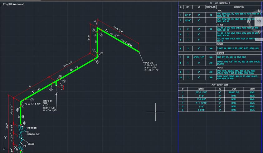
Pipe spool drawings consist of three sections: main graphic, bill of material, and title bar.
Main Graphic Section
The main graphic section consists of the isometric representation of the pipe line route in 3D space, and also includes the following details:
- Flow Direction.
- Line Number.
- Weld Locations.
- Piping Components location.
- Support Tags and location.
Bill of Material Section

The bill of material section for the portion of line shown in an isometric graphic is depicted on the left or right side of the drawing. It includes the following details for all components:
- Nominal Size.
- Quantity.
- Component Description.
- Component Material Code.
- Number of Spools.
- Shop material or field material.
Title Bar Section
The title bar section can be found at the very bottom of the isometric drawing and contains project details such as client name, engineering office name, project name, project number, process licensor etc. In addition, pipe lines detail line size, line number, tracing, insulation, fluid code, operating and design pressure/temperatures, test pressure, piping material class etc.
Issued for Fabrication Drawing
Pipe spool drawings are for the sole use of the equipment provider or integrator only. They are not provided to the client for approval and are issued directly to the subcontractor (if applicable) and the fabrication floor. After the isometric drawing is released to the shop floor, the redlining of drawings is typically allowed by a fabricator, designer, or engineer.
Prerequisites and Checking Procedure

Before piping arrangement and isometric checking starts, certain engineering documents must be completed. The checker is responsible for obtaining and using the most recent copy of the following:
- Instrument list and datasheets.
- Piping classes.
- Piping standards.
- IFC P&IDs.
- Model review comments (if applicable).
- Final stress isometrics.
- Equipment check files.
How to Read a Pipe Spool Drawing

Pipe spool drawings are oriented on the grid relative to the north arrow shown on drawing plans. The pipe line number (ex. 2”-WPR-8547-01) indicates the fluid service, piping class and material, insulation details, and is usually drawn in a single isometric right. The pipe lines are presented as straight lines while fittings (i.e elbow, tee, reducer) are depicted as curved lines that attach to the pipe lines via an appropriate welding machine and process. Connected valves are depicted with a symbol already provided in the P&ID. Referring to the above image, The 2″ and 1″ represent the sizes of the given pipe.
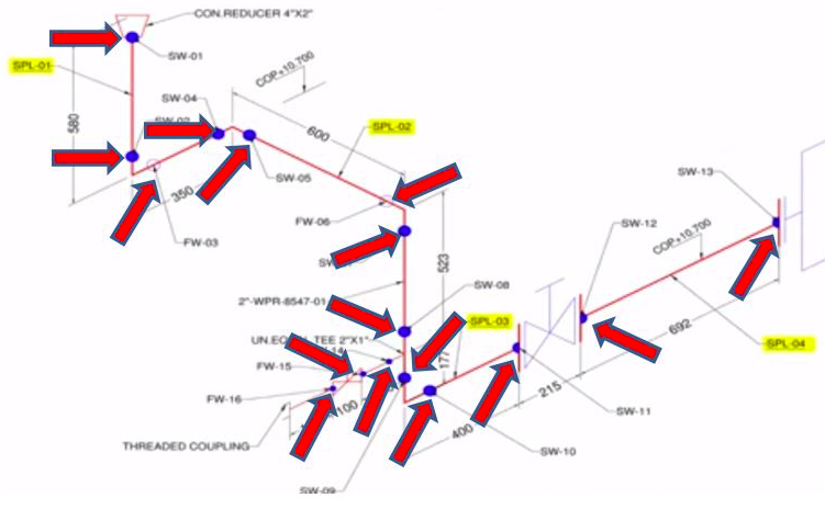
It is also necessary to know the total number of joints. As depicted in the image above, there are a total of 16 joints. Joint 1 to 13 has a pipe size of 2″, while joint 14 to 16 has a pipe size of 1″. These joints are welded. In the drawing, ‘SPL-02’ indicates the spool number of 2. Hence, in the provided image there are a total of 4 prefabricated pipe spools available. These can be seen as SPL-01, SPL-02, SPL-03 and SPL-04. Associated pipe fittings will be drawn in the piping isometric and depicted with symbols.
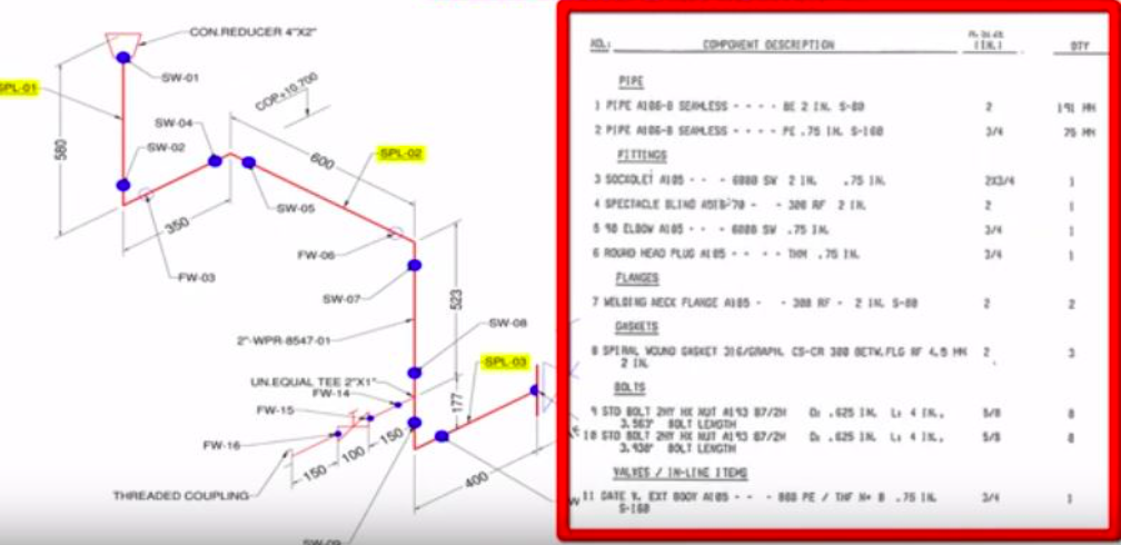
The Bill of Materials section of the drawing can also be utilized to grasp and obtain more insight on the affiliated drawing, as this section will depict all pipe line numbers, total fittings and types, and further component descriptions. For complicated piping systems or ones that end or originate from a pipeline header, individual pipe runs are represented on separate isometric diagrams.
Using a Pipe Spool Drawing

Pipe fitters and welders utilize the pipe spool drawings as a guide to fit and weld a pipe spool. It is also a useful MEP (Mechanical, Electrical and Plumbing) tool for plumbers as it allows them to understand how to assemble a pipe spool along with its associated components. In rare cases, engineers may use pipe spool drawings for situations where a ship loose pipe spool must be integrated into a system. Common usages of piping isometrics include, but are not limited to:
- Pipe fitting.
- Pipe welding.
- Quality checks.
- Maintenance of components.
- Stress analysis.
- Preliminary bulk material take off (MTO).
Pipe Fitting
Pipe fitters utilize the pipe spool drawings to locate and install fittings into their appropriate space. They are also used to pinpoint and repair broken pipe fittings that cause flow disturbance within the piping system. Welding connects the pipe fittings to pipe lines.
Pipe Welding
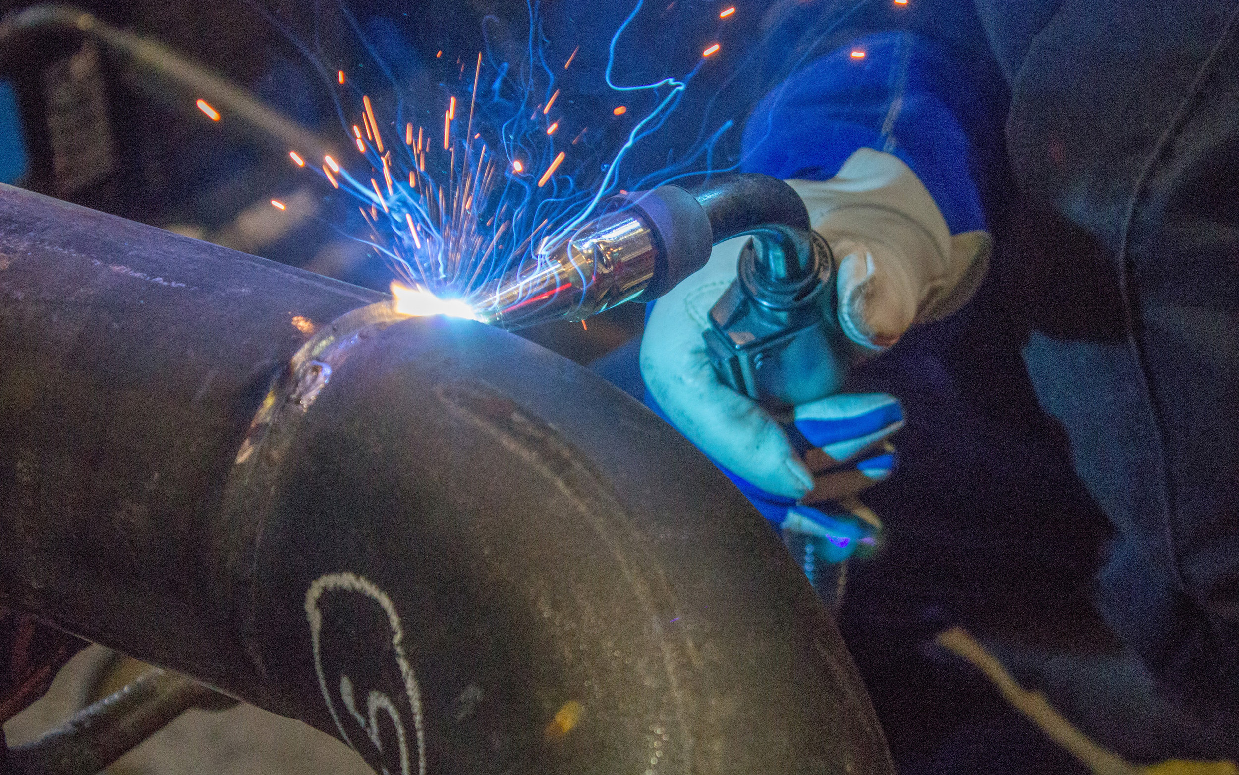
Pipe fabrication, or pipe welding, enables two pipes to join together and provides great durability. This process is achievable through a variety of welding methods, such as:
- MIG Welding (Metal Insert Gas)
- TIG Welding (Tungsten Insert Gas)
- SMAW Welding (Stick Metal Arc)
Stick metal arc welding is typically the most common type of welding and is a daily activity at pipelines and at fabrication facilities. Pipes must be prepared diligently prior to the welding phase, ensuring that the edges to be joined are smooth, uniform, and aligned properly. Welders should become certified by passing required welding tests and use a high-quality welding machine.
Quality Checks
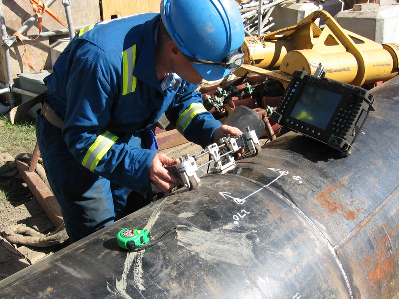
The purpose of any quality check is to verify that all the specifications, drawings, and other deliverables reflect the exact combination of the issues impacting the end product. These include, but are not restricted to:
- Function
- Safety
- Operability
- Constructibility
- Mechanical integrity
- Mathematical accuracy
Checking, or the quality assurance and quality control (QA/QC) of piping runs, is necessary to prevent failures or malfunctions. Poor QA/QC practices result in incorrect fabrication, leading to costly rework.
Poor QA/QC may occur as a result of late changes to the P&ID, vendor drawings, or data from another discipline. All materials and equipment involved in the “Bill of Materials” must be validated for approval. This, along with the weld verification is done via non-destructive testing. The piping isometric contains all information necessary to purchase the correct material, fabricate the piping configuration, and install the line or system complete with testing and check-out.