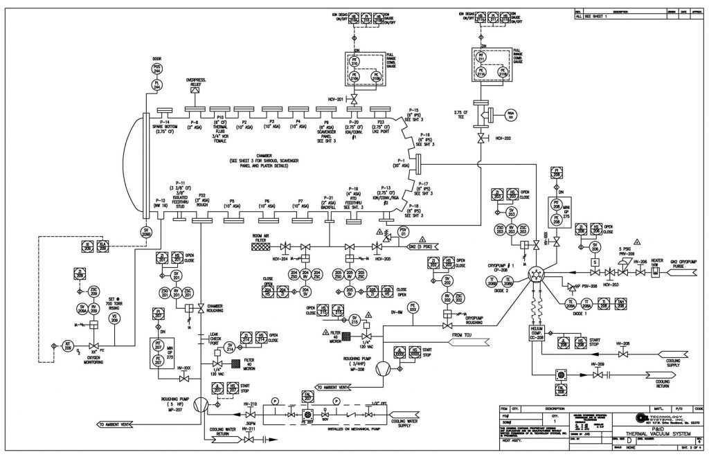
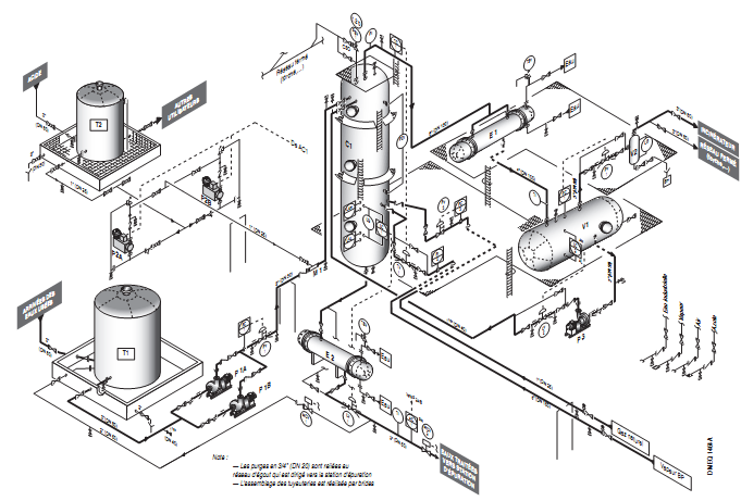
The P&ID, also known as the Piping and Instrumentation Diagram, is an end to end schematic that displays major process details of a system. P&IDs show operating conditions, major equipment, valves, and instrumentation required to run, monitor, and control a specific process. It is typically the first major deliverable for an equipment provider and provides the system design for all subsequent documents. In this article, we will discuss the process for generating a P&ID, how to read a P&ID, and using a P&ID for document generation and equipment verification.
Process of Generating a P&ID
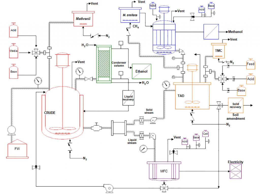
The project engineer typically assumes responsibility for generating the P&ID and may work with multiple engineering disciplines/drafter in concert. P&IDs do not describe the chemical reactions involved nor provide operating and maintenance procedures. P&IDs provide flow direction, valving, instrumentation, major equipment details and operating parameters. Depending on system complexity and scope definition, the P&ID may have been prepared during the proposal phase. Generating a P&IDs requires a strong knowledge of equipment data sheets, project specifications, and system operating behavior. In some organizations, much of this work is automated via a smart P&ID process.
The following stages describe the process for generating a P&ID.
Create Symbol P&ID Legend
It is ideal for a Symbol P&ID Legend to be generated first. A Symbol P&ID Legend (Reading instructions shown below) is a document that depicts all the symbols and labels used in the main P&ID. Creating a Symbol P&ID Legend prior to the design stage help project engineers organize and keep track of the systems process flow efficiently.
P&ID Design Stage
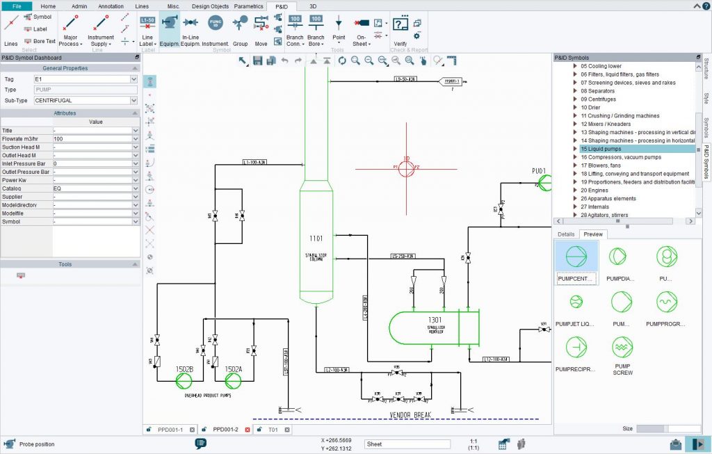
Project engineers, sometimes in conjunction with a drafter, use a computer-aided drafting tool (CAD) to generate a P&ID. Engineers list the elements in a standard P&ID. The list must include all piping elements and the placement and order of the following:
- Valves
- Branches
- Control interlocks
- Equipment
- Instrumentation
- Reducers
Next, symbols from the symbol P&ID are configured in the system. Depending on the system, the configuration will be modified. Following the configuration comes the connection of pipes and other equipment. The project engineer may collaborate with multiple engineering disciplines to create the optimal process flow. During the connection phase, the project engineer may ask the following:
- What action/actions causes this process?
- What happens next?
- Does the unit require special configuration?
- What equipment is necessary for the next step?
The project engineer then reviews the details with colleagues, comprised of an interdisciplinary team whenever possible.
Finalize P&ID
Comprehension of the process flow is imperative as one small error could compromise the entire system. It is also necessary to walk through the stages several times and look for inefficiencies and errors. The P&ID is then shared with collaborators and finalized. During operation, P&IDs must be maintained to show actual plant conditions at any time and be updated when any physical changes are made to the system.
Reading a P&ID
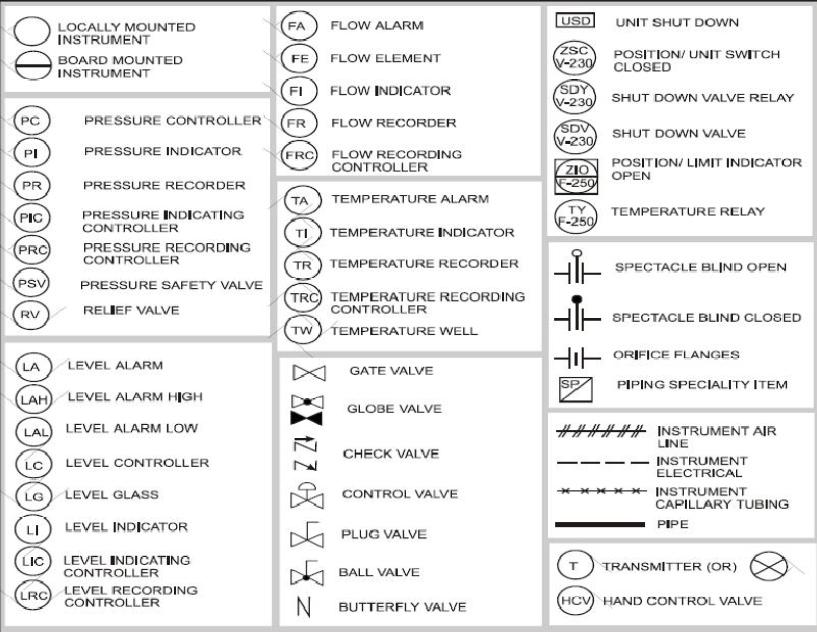
Comprehension of the Legend is crucial to using a P&ID. The Legend Sheet identifies the symbols and labels utilized in the accompanying set of P&IDs. The Legend section is normally found on the front page and standardizes the symbols used in the P&ID.
Details of the Legend sheet will vary by manufacturer, but will follow a similar standard format as shown below.
Tagging
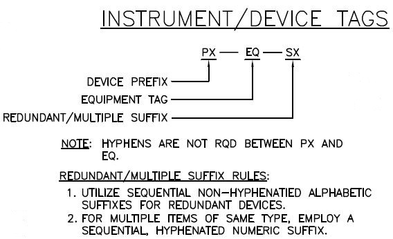
Figure 1 Instrument/Device Tags
All items must be identified with a tag. Tag Identifiers (Tag ID) are depicted within the equipment symbol on large items (e.g tanks and vessels), or underneath the item if it is small (e.g pump and filters.) Tag IDs are unique to the equipment and consist of a standard prefix, a unique equipment number that is derived from the system number, and a sequence number. Pump and compressor Tag IDs indicate the system and type of pump being depicted.
Piping Identification Chart
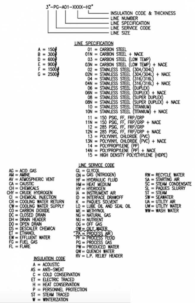
Figure 2 Piping Identification Chart
The standard Piping Identification Chart distinguishes pipings used in the system. Every length of pipe in the set is identified with a tag that determines the unique piping identifier. Specifications for the piping line hold true until another specification is stated. This point is known as a spec break. The line number is produced from the two-digit system number with a line-specific two-digit number.
Valve Identification System
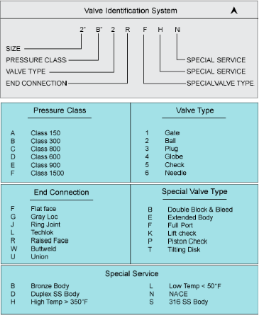
Figure 3 Valve Identification System
Valves are distinguished using the Valve Identification System. This table is used for every valve above a specified size (generally 2”) and is read similarly to the Piping Identification Chart. Valves are identified according to size, pressure class, type, connection, special valve type, special materials and special insulation requirements. Control valve symbols are concerned more with the mode of operation than the valve type used, and are drawn as a gate type (gate valves not used for controlling flow). As shown in figure 3, the identified valve is denoted with its own unique designated identification line (2” B 2 R F H N). Some operation teams label valves with a system specific number for ease of use.
Piping Symbols
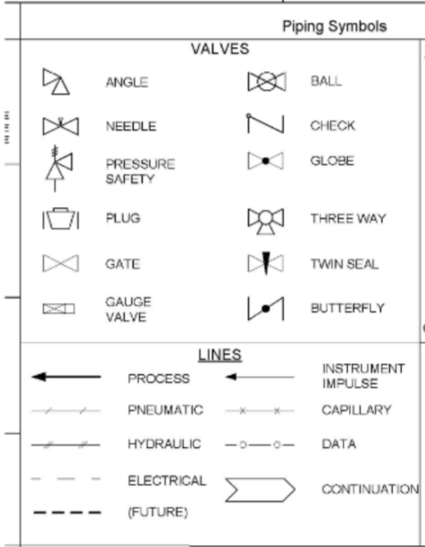
Figure 4 Piping Symbols
Piping symbols are the structure of the P&ID. Diagrams representing piping, instrumentation connections, valves, smaller components and specific information on operating the process are presented within Piping Symbols. Since there is no standard method of showing equipment on a P&ID, each symbol can vary per project. For example, the gate valve symbol (as shown in figure 4) can be depicted as a different shape. Miscellaneous components and abbreviations are also provided in this section. Understanding a P&ID requires recognition of every symbol portrayed in the Legend.
Equipment Symbols
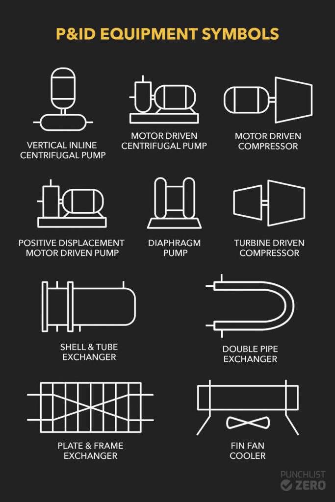
Figure 5 Equipment Symbols
Equipment Symbols generally resemble the equipment concerned. They indicate the name and relative size of the equipment, but are not drawn to scale. Equipment descriptions will have specific information such as capacity or actual size. The symbols also identify important pieces of equipment and connections that are attached to/within the part. Abbreviations are reasonably generic (e.g ‘NO’ means Normally Open.) Note that each P&ID will use different symbols to represent the equipment.
Instrumentation
Within the P&ID Legend may be several pages dedicated to Instrumentation. The Instrument Symbols and Legend sheet(s) contain the instrumentation identification standard in use for the entire set of P&IDs. The standard format can be seen below.
Instrument Identification System
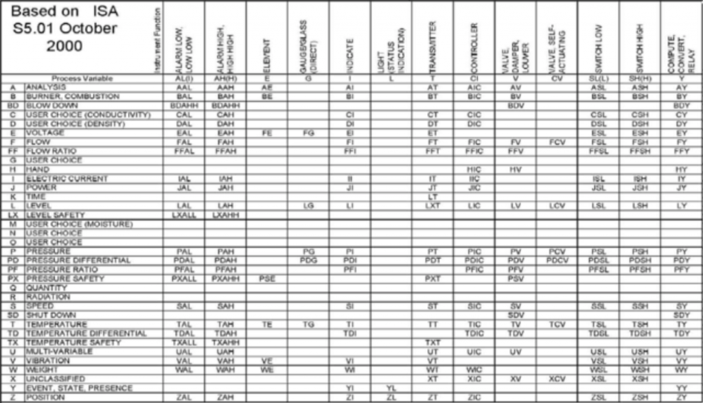
Figure 6 Instrumentation Identification System
Figure 6 depicts a consistent scheme for instrument identification. Every instrument identifier begins with a letter identifying the process variable that the instrument is concerned with. Start from the left hand column to identify the concerned process variable (e.g ‘W’ for Weight) and follow the row to the right to find the remainder of the identifier (e.g ‘WE’ for Weight Element.)
Instrument Symbols
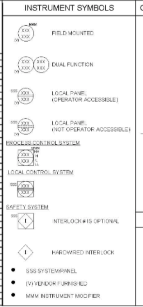
Figure 7 Instrument Symbols
For P&IDs, instrument identification is generally given in a disk (meaning field mounted instrument(s).) Symbols shown in Figure 7 are not standard and may differ from site to site. Valves in a control loop will be given inside a disk drawn adjacent to the valve and connected with a thin diagonal line. The three-letter symbol located at the left of the disk indicates the safety system instrumentation and panels. Actions available are noted to the right of the box.
Flow Symbols
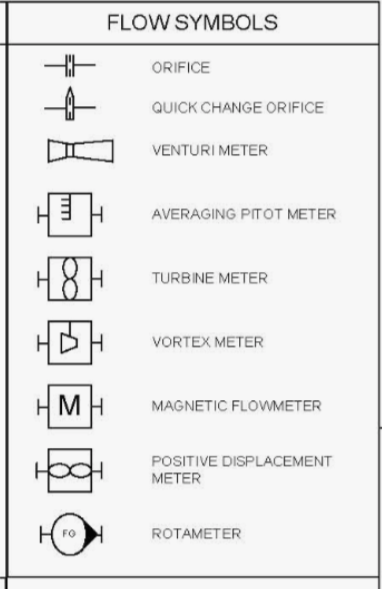
Figure 8 Flow Symbols
The P&ID utilizes various flow symbols to show the differing methods of flow measurement in use. Figure 8 contains a collection of flow meters that should not be taken as comprehensive. The symbols depict how flow is measured by the flow element (FE), which sends a signal to the flow transmitter (FT), that sends a signal to the flow indicator (FI) or Flow Controller (FC).
Design Temperature
Process engineers determine the Operating Temperature which is temperature the equipment and piping system during operating. Temperatures can differ from those required for intended operation (e.g starting up and shutting down.) The highest temperature that provides flexibility for the control of intended operation is the Maximum Operating Temperature (MOT). MOTs serve as the basis for materials selection in regards to long term corrosion/material degradation. Operating Temperature is equal to the MOT in cases when flexibility is not required. Design Temperature is higher than the max temperature to which the equipment may be subjected.
Using a P&ID

P&IDs provide important information for manufacturing, installing equipment/machinery, piping, instrumentation, and correct operation of the plant. While P&IDs are applied in a variety of methods, typical uses of a P&ID can be seen below.
Document Generation
Because P&IDs hold dense and valuable information about a plants structure, process details, and instrumentation required to run, they enable various other documents to be generated. Examples of generated documents include: general arrangements, isometric drawings for piping, instrument lists, cause-and-effect diagrams, control philosophy, plot plans, etc. Due to its immense universal applicability, P&IDs are referred to as “primary interdisciplinary documents.”
Equipment Verification
P&IDs can also be applied for equipment verification. Project engineers and mechanical designers apply P&IDs to verify proper system functionality, such as the following.
- Components are correctly tagged/sequenced.
- Manual valves can operate through full range.
- Piping/tubing is installed with the correct diameter.
- Connection types are specified as in the drawing.
- Housings and valves installed in the correct orientation
- No deadlegs are present.
- Sample points present and accessible
P&IDs also allow for assessment of construction processes, serve as a foundation for programming controls, and allow for the production of instructional documents. They may allow for the creation of facility operation standards and plant operational standards as well as serving as the basis for a hazard and operability study (HAZ-OP).