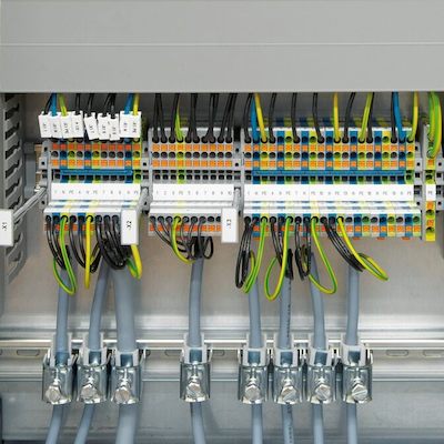
Control wiring is a physical mode of communication between control devices used to transmit commands. Sometimes referred to as the nervous system of the control system, control wiring connects all the parts for proper functionality. Instrumentation and system performance is contingent on the proper choice and installation of control wiring.
Line Voltage Wiring
Line voltage wiring provides power and load connectivity for the equipment with power ranging from 120 to 277VAC. It can also provide travelers to multi-way applications in most of the cases. Usually, line voltage wiring uses a circuit/switch leg for grouping the light fixtures. The wiring is based simply on/off the functionality of the circuit and On/Off control. Power-line carrier communication, as well as switching signal functionality, can be achieved by line voltage wiring. It has the advantage of providing both power and communication. However, functionality is limited as circuiting zones are fixed. It also requires the installation of protected raceways such as conduit, leading to an increase in installation costs. Line voltage wiring can run in conduit with other line voltages so it is suitable for projects where existing wiring is already present.
Dedicated Control Wiring
Dedicated control wiring is used whenever more functionality and flexibility is required. Dedicated control wires are low voltage wiring and can be a pathway for digital or analog signals. They do not require conduit, making it flexible and easy to install by just using plenum rated wiring on the top. There are differences in the functionalities of analog and digital dedicated control wirings.
Analog Wiring
Two wires with a voltage difference of between them form the basis of analog wiring. It does not require conduit installation, however, drawbacks of poor signal to noise ratio may be experienced without conduit. In addition, sensitivity to polarity and fixture to fixture light output variations can be experienced when dimming across long runs. Stranded copper wires sizes range from 22AWG to 14AWG. Since this low voltage wiring is sensitive to electrical and electromagnetic noise of the surroundings, it is best to use shielding to avoid such problems.
The most commonly used analog wiring control system is a 4-20mA current loop. A 4-20mA current loop consists of a sensor, transmitter, power source, loop wire, and receiver.
Sensor
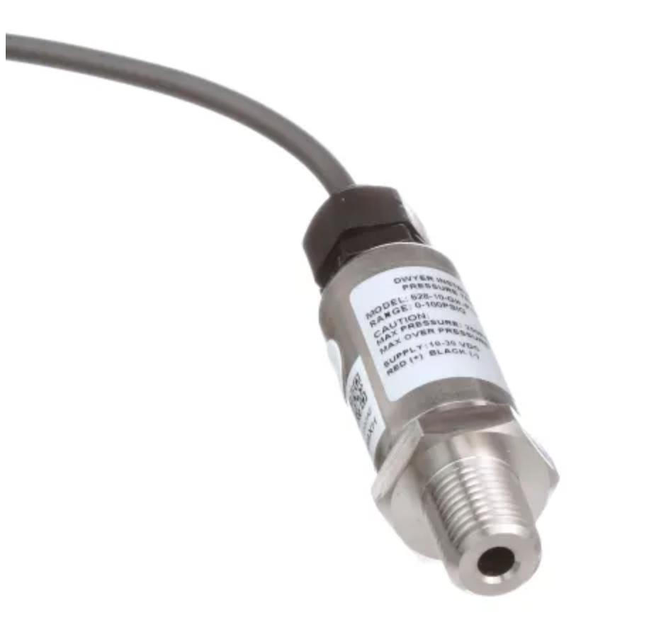
Sensors detect a process variable, typically temperature, pressure, and flow rate. Sensors transmit data readings to a transmitter.
Transmitter
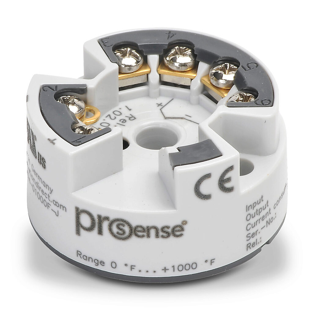
A transmitter converts sensor data readings to current readings. Sensor data readings range from 4 to 20mA. 4mA maps to the minimum possible value of the sensor and 20mA maps to the maximum possible value.
Power Source
A power source generates the signal. Applied voltage levels differ but applied voltage should be greater by at least 10% of the voltage drop of the components present in the loop. Otherwise, lesser voltages can fail equipment.
Loop Wire
This is the wire that connects the sensor to the device at receiving end of the 4-20mA signal. The loop also consists of the connection back to the transmitter side.
Receiver
The receiver interprets the electric signal and performs the required operation based on that signal. The required operation may be the shut-off of a valve, an increase in pumping power, or a similar mechanical operation.
Digital Wiring
Like analog wiring, two wires provide signaling information. Digital wiring results in a simpler and more elegant electric configuration as it forms a single bus that connects all control devices. These wires draw comparatively very little current and binary messages transmit the required commands. Using the digital binary mode of messages has lots of benefits, including resistance to external electric and electromagnetic interferences.
The same communication protocol must be deployed on all the devices for proper communication. Commonly used communication protocols are RS485, LON, and DALI.
RS485
RS485 uses a pair of twisted small gauge wires along with a shield conductor and has the capacity for runs of up to 4000 ft. Drawbacks include sensitivity to polarity and linear topology requirements.
LON
LON is not polarity sensitive like RS485. As such it uses an unshielded twisted pair of wires. It also permits open topology, but has a limited range of 1,500ft. Repeaters are required for any run over 1,500 ft.
DALI
DALI does not use twisted wires and gives freedom of not being topology specific and polarity sensitive but is slower in transmission. In addition to its slow speed, the number of maximum nodes that can be attached to it is also limited.
Applicable Codes
The adherence to national and local building codes is required during the specification and installation of control wiring. The most frequently referenced code for wiring compliance is the National Electrical Code.
National Electric Code
The full NEC requirements cover an electrical range of electrical wiring, components, and installation. For purposes of this article, only several major concerns in control wiring as it pertains to wiring runs, terminations, and integration are reviewed. For a complete understanding of the applications of NEC code, professional instruction is recommended.
Wiring Runs
Power cabling and should never be installed in the same conduit or wire way with dedicated control wiring as interference will result. Raceways must be sized so that conductors can be easily pulled and enough space is allotted between each conductor to prevent overheating. As per NEC, fill should be limited to 40% for over 2 conductors, 31% for only two conductors, and 53% for one conductor for standard raceway applications.
The exception to these percentages is when wire is used in seal-offs and nipples. For seal fittings, the fill may not exceed 25%. This is not specifically stated in the code, but is interpreted through the requirement that listed items be used in accordance with their listing. UL lists seal fittings for 25% fill. Nipples are defined as a conduit 2 feet or less in length and connect enclosures, boxes, gutters, wireways, etc., together. By applying the 60% rating, nipples do not have to be derated and more conductors can occupy the raceway.
Cable Sizing
Cables must be sized so that the maximum combined voltage drop for both the feeder and branch circuit shouldn’t exceed 5%, and the maximum on the feeder or branch circuit shouldn’t exceed 3%. Cables should not be excessively oversized as they may not be able to fix on designated termination blocks, and the heavier weight may create additional support concerns.
Terminations
As per NEC Section 110.3(B), all terminations are to be installed with equipment listing, labeling, and instructions. All terminations must be marked with torque values or where instructions provide the torque values must be properly torqued.
IEC 60364 – Electrical Installations in Buildings
IEC 60364 is published by the International Electrotechnical Commission and is the governing electrical code in Europe. In contrast to the National Electric Doe, the IEC 60364 only provides guidance. It does not establish overcurrent protection and as such may not be appropriate to use as a sole guideline for control wiring installation.
System Integration
Control wiring is part of an instrumentation system that provides real-time information and controls to deliver process requirements. Two main control systems exist: programmable logic controllers and distributed control systems.
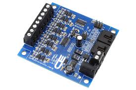
Programmable Logic Controllers
The simplest type of control units working independently in discrete units with one loop each unit. Complex control systems can be created using networks of these programmable logic controllers by letting them communicate using industry-standard protocols. This infrastructure is applicable up to a specified number of loops and after that distributed control systems are preferred.
Distributed Control System
In a distributed control system, control modules are distributed throughout the system. This provides easy configuration methods of control systems within plants through the use of cascaded loops and interlocks. In large systems, DCS is preferred over an amalgamation of discrete controllers due to their cost-effectiveness, reliability, and scalability.