Etukudo
Minor losses in pipes stem from a divergence in flow direction, diameter change, and the presence of disturbances. They do not include frictional (major) losses, which are the result of fluid-pipe wall interaction in straight pipes or ducts. In this article, you will learn more about minor losses, how to calculate them, and if minor losses may be ignored in a flow system.
What are Minor Losses?
Minor losses in pipes are pressure losses due to changes in the velocity of a flowing fluid. Factors that can result in velocity change include:
- Presence of pipe fittings such as valves, chokes, and other appurtenances.
- Head loss due to bend in the pipe.
- A sudden enlargement or contraction of the flow diameter.
- Also, head loss at the entrance or exit of a pipe.
- Pressure loss due to an obstruction.
The presence of these features result in flow disturbance, which causes eddy formation, and eventually, head losses. Although this type of loss goes by the name ‘minor’, they could constitute a significant portion of the pressure losses in a piping system. For example, the minor loss for a valve that is closed or almost in the closed position is infinite. Also, a relatively short piping system with several bends and fittings could have minor losses exceeding the major losses.
When estimating the total head in a pipe, the three important forces that contribute to it are the elevation head, pressure head, and velocity head. Because minor losses directly relate to the velocity head, its values usually increase with flow velocity.
How to Calculate Minor Losses in Pipes
The combination of minor and major losses is important in the estimation of the total head in any piping system. Generally, there are two approaches to calculating minor losses, which are the K-value method and the equivalent length method.
K Method
The K-value, otherwise known as the minor loss coefficient, is a dimensionless number. It describes the influence that a fitting or elbow has on the minor losses in a system, and is unique to the type of fitting. For a particular fitting or elbow, the minor loss (hm) is a product of the K-value and the velocity head, which is a combination of flow velocity (v) and gravity (g).
![\[ h_{m}=K\left ( \frac{v^{2}}{2g} \right ) \]](https://punchlistzero.com/wp-content/ql-cache/quicklatex.com-676e6849923e8406bc9005aea2639330_l3.png "Rendered by QuickLaTeX.com")
When there are multiple fittings along a pipe section, the total K-value is a summation of the K-value of each fitting. The total head loss (hl) in the system can then be found by adding the minor loss to the major loss as follows:
![\[ h_{l}=\left ( \frac{fL}{D}+\sum K \right )\left ( \frac{v^{2}}{2g} \right ) \]](https://punchlistzero.com/wp-content/ql-cache/quicklatex.com-7325db00fb2e148435e2f5f921b438d7_l3.png "Rendered by QuickLaTeX.com")
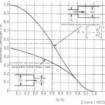
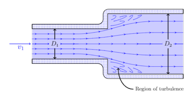
Whenever there is a sudden expansion or contraction of flow, the expression for the minor losses changes slightly. Because the pipe diameters are different, the flow velocities are also different, which changes the minor loss expression as follows:
![\[ h_{m}=\frac{\left ( v_{1}-v_{2} \right )^{^{2}}}{2g} \]](https://punchlistzero.com/wp-content/ql-cache/quicklatex.com-796574d8ff7da450dc3a17752f280efc_l3.png "Rendered by QuickLaTeX.com")
An advantage of using the K-value in estimating minor losses in pipes is that it captures the impact of flow regimes. As a result, it is more accurate than the equivalent length method. Examples of K-values for some fittings are in the following table.
| Fittings | K |
| Elbows | |
| Regular 90°, flanged | 0.3 |
| Regular 90°, threaded | 1.5 |
| Long radius 90°, flanged | 0.2 |
| Long radius 90°, threaded | 0.7 |
| Long radius 45°, flanged | 0.2 |
| Regular 45°, threaded | 0.4 |
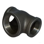
| Tees | |
| Line flow, flanged | 0.2 |
| Line flow, threaded | 0.9 |
| Branch flow, flanged | 1.0 |
| Branch flow, threaded | 2.0 |
| Union, Threaded | 0.08 |
| Valves | |
| Gate, fully open | 0.15 |
| Gate, ¼ closed | 0.26 |
| Gate, ½ closed | 2.1 |
| Gate, ¾ closed | 17 |
| Globe, fully open | 10 |
| Ball, fully open | 0.05 |
| Ball, 1/3 close | 5.5 |
| Ball, 2/3 close | 210 |
Equivalent Length Method
The equivalent length method equates the head loss of a valve/fitting to a pipe length that would cause equivalent friction loss. As a result, this equivalent length (LE) of pipe can be integrated into the Darcy-Weisbach equation as follows:
![\[ h_{l}=\left ( \frac{f\left ( L+L_{E} \right )}{D} \right )\left ( \frac{v^{2}}{2g} \right ) \]](https://punchlistzero.com/wp-content/ql-cache/quicklatex.com-ee323dbc7707e65970cf1472e6bb7a0a_l3.png "Rendered by QuickLaTeX.com")
Using this approach, the minor losses in all fittings, elbows, and tees can be aggregated into a pipe length and the frictional loss calculated. The equivalent length is experimentally determined and applies to all sizes of a type of fitting. Moreover, this is achieved by dividing the length by the flow diameter of the fitting to make it a dimensionless number. Common equivalent length values can be found in various fluid mechanics documentation as the example below shows.
| Fitting Type | LE/D |
| Gate valve, fully open | 8 |
| Ball valve, full bore | 3 |
| Ball valve, reduced bore | 25 |
| Globe valve, fully open | 320 |
| 90° screwed elbow | 30 |
| 90° long radius bend | 13 |
| 45° screwed elbow | 16 |
| 45° long radius bend | 10 |
| Welded tee, thru-run | 10 |
| Welded tee, thru-branch | 60 |
Unlike the K-value, equivalent length does not vary with flow velocity and pipe geometry, so it is insensitive to flow regime. Thus, it is not as accurate as the K-value approach.
Can Minor Losses Be Ignored?
Generally, minor losses in pipes are small in comparison to friction losses, especially in long pipes. In such systems, the interaction of the fluid and pipe wall takes a heavy toll on the flow energy. Thus, the contributions of infrequent occurrences of valves, tees, bends, and other fittings along the flow are insignificant.
However, as the pipe length gets shorter, the proportion of head loss due to appurtenances gets larger. So, overlooking them could result in a serious error. Another factor to consider is the flow conditions. When flow velocity is high, there is an increase in the velocity head of the system, and consequently, an increase in minor losses. Also, if there are several valves not in the fully open position, the contribution of minor losses could be significant.