Etukudo
A concrete corbel is a short cantilever protruding from a wall, column, or the side of a beam. In this article, you will learn the purpose of a concrete corbel, the design process, and the use of steel beam in corbel design.
Purpose of a Concrete Corbel
Generally, corbels act as brackets that transfer vertical and horizontal forces from beams to walls or columns. This holds especially true in precast or reinforced concrete structures. Of necessity, they are built into walls at a depth that is sufficient for the pressure of the embedded portion to counteract the load on the exposed portion. Otherwise, failure may result. Although concrete corbels are primarily load-bearing elements, their design often takes a variety of shapes to improve the aesthetics of the structure.

Concrete Corbel Design Process
There are several codes that govern the design of concrete corbels depending on the location of the application. Some examples include the ACI 318-14, IS 456:200, BS 8110, and Eurocode 2. To provide a brief overview of the process, this section references the ACI 318-14 and covers geometric, load, and reinforcement requirements. Note, that all formulas and terms in the following sections are in metric units.
Geometric Requirements
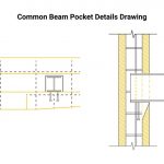
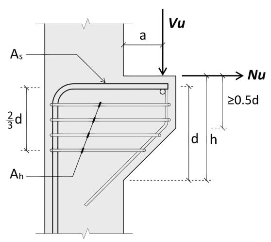
Below is a figure that shows the basic dimensions necessary for the design of a concrete corbel.
Generally, a concrete corbel has a trapezoidal shape, and the geometric requirements from ACI for this shape are:
- There should be a minimum dimension of 0.5d for the outer depth at the edge, as the figure above indicates. Where the parameter d represents the effective depth, which is the height of the corbel that reinforcements cover.
- Next, the span-to-depth ratio (a/d) should not exceed 1.0. For corbels, span (a) refers to the distance between the wall or column and the load-bearing point on the corbel.
Load Requirements
According to section 16.5.2.4, the nominal vertical load (Vu/φ) is the characteristic vertical load used in design analysis. Moreover, it is a ratio of the vertical load (Vu) to the strength reduction factor (φ) as specified by the code. For evaluating the flexure, axial, and shear-friction strength of a concrete corbel, the code recommends a strength reduction factor of 0.75.
So, for a normal-weight concrete, this nominal vertical load should not exceed the smallest of the following resistance values:
[Latexcode]
![\[ 0.2f_{c}^{'}b_{w}d \]](https://punchlistzero.com/wp-content/ql-cache/quicklatex.com-d84127a22e9f389ec3a8480babdd0497_l3.png "Rendered by QuickLaTeX.com")
![\[ \left (3.3+0.08f_{c}^{'} \right )b_{w}d \]](https://punchlistzero.com/wp-content/ql-cache/quicklatex.com-646a563a5e9497a5636c0c43a73fc152_l3.png "Rendered by QuickLaTeX.com")
![\[ 11b_{w}d \]](https://punchlistzero.com/wp-content/ql-cache/quicklatex.com-4ec99078f9adfc0fd7ccecb9c5ef3f30_l3.png "Rendered by QuickLaTeX.com")
Where bw is the corbel width and fc is the concrete strength.
For the case of light-weight concrete, the nominal vertical load should not exceed the smallest of the following:
[Latexcode]
![\[ \left ( 0.2-0.07\frac{a}{d} \right )f_{c}^{'}b_{w}d \]](https://punchlistzero.com/wp-content/ql-cache/quicklatex.com-b0a8c1d086f2a6c4eddeef350a012528_l3.png "Rendered by QuickLaTeX.com")
![\[ \left ( 5.5-1.9\frac{a}{d} \right )b_{w}d \]](https://punchlistzero.com/wp-content/ql-cache/quicklatex.com-a438c4e65db83e92b40ba08454aa07ac_l3.png "Rendered by QuickLaTeX.com")
Some other loading conditions necessary for providing a structurally sound design are:
- The maximum horizontal load (Nu) should be less than or equal to the vertical load (Vu).
- Also, the minimum horizontal load should be greater than 20% of the vertical load.
The second condition above, which is for the minimum horizontal force, can be ignored if there are alternative means to prevent tensile load transfer to the corbel. For example, the provision of horizontal sliding bearing supports would be such a case.
Reinforcement Requirements
The ACI code also specifies how to determine the adequate reinforcements for a concrete corbel. Moreover, these reinforcements include tensile, shear-friction, and flexure. For instance, the axial tensile reinforcement is governed by the area of reinforcement (An) within the corbel that is resisting tensile force. Equation 16.5.4.3 gives the formula to calculate this area, and it is a function of the horizontal force (Nu), strength reduction factor (φ), and the reinforcement yield strength (fy).
[Latexcode]
![\[ A_{n}=\frac{N_{u}}{\varphi f_{y}} \]](https://punchlistzero.com/wp-content/ql-cache/quicklatex.com-c792e342cd31dfa5e260513083c156f7_l3.png "Rendered by QuickLaTeX.com")
As for the area of the reinforcement resisting shear-friction (Avf), it is a function of vertical load (Vu), strength reduction factor (φ), the reinforcement yield strength in the vertical direction (fyv), and friction coefficient (μ).
![\[ A_{vf}=\frac{V_{u}}{\varphi \mu f_{vy}} \]](https://punchlistzero.com/wp-content/ql-cache/quicklatex.com-45339e4e61bb91f3aab877040ca785ff_l3.png "Rendered by QuickLaTeX.com")
Finally, the area of flexure reinforcement (Af) of a concrete corbel is dependent on parameters already identified plus a factored moment (Mu).
![\[ A_{f}=\frac{0.85bdf_{c}^{'}}{f_{y}}\left [ 1-\sqrt{1-\frac{M_{u}}{0.425\varphi bd^{2}f_{c}^{'}}} \right ] \]](https://punchlistzero.com/wp-content/ql-cache/quicklatex.com-3dc5104ab2be7c5b52d55593b5d8dd04_l3.png "Rendered by QuickLaTeX.com")
Then, after determining these three reinforcements, the code recommends selecting the governing reinforcement as the largest of the following values:
![\[ A_{f}+A_{n} \]](https://punchlistzero.com/wp-content/ql-cache/quicklatex.com-18184e90044f3e464fdfa9eec61c9a93_l3.png "Rendered by QuickLaTeX.com")
![\[ \frac{2}{3}A_{fv}+A_{n} \]](https://punchlistzero.com/wp-content/ql-cache/quicklatex.com-1ee98867a14c0985ec816c031fa07a11_l3.png "Rendered by QuickLaTeX.com")
![\[ 0.04\left ( \frac{f_{c}^{'}}{f_{y}} \right )b_{w}d \]](https://punchlistzero.com/wp-content/ql-cache/quicklatex.com-b8a3af648e1bccb7040016036286ee33_l3.png "Rendered by QuickLaTeX.com")
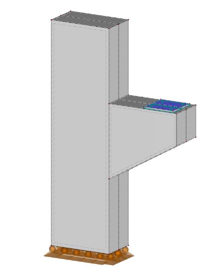
Use of Steel Beam in Corbel Design
Traditionally, structural engineers treat steel structures and concrete structures as separate. But, in recent times, the combination of both materials in a single structure is common, because of the benefits each has to offer. For example, using a concrete column with a steel beam, instead of a steel column, can provide better fire protection in a building. In such scenarios, the connection between the concrete corbel and the steel beam constitutes a grout, base plate, and anchor bolts.
It is important that this connection provides sufficient resistance against the tensile, bending, and shear loads from the corbel design. Alternatively, if steel columns are in use, then the corbels shall be steel also. Moreover, these offer superior strength features and sustainability. Also, their short lead time makes them ideal for quick construction projects.