Etukudo
An eccentric load is one that acts on a structural member at any point other than the member’s centroid. In this article, we will review the definition and mechanics of an eccentric load, some examples of it, and its impact on footings.
Definition and Mechanics
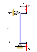
Eccentric loads are those whose line of action is offset from the axis of a member. Moreover, the distance between the geometric axis and line of action of the force (P) is the eccentricity (e) of the load as the diagram below shows.
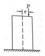
Generally, the design of structures is such that the line of action from loads passes through its center of gravity to ensure uniform stress distribution. But when loading is eccentric, the structure becomes prone to a significant increase in bending stress in addition to the direct stress.
Bending Stress from Eccentric Load
One of the effects of eccentric loading is the development of bending moment (M) on the structure. Moreover, this moment is a product of the load and the eccentricity.
![\[ M=P\times e \]](https://punchlistzero.com/wp-content/ql-cache/quicklatex.com-b36336ae9b1a4eeef29b65093aee80c4_l3.png "Rendered by QuickLaTeX.com")
As a result, there will also be a bending stress (σb). This stress is a function of the moment area of inertia (I), and the distance (y) between the neutral axis and point of determining bending stress.
![\[ \sigma _{b}=\frac{M\times y}{I} \]](https://punchlistzero.com/wp-content/ql-cache/quicklatex.com-0de4c0da041bda98ffde16ef0b4eda5f_l3.png "Rendered by QuickLaTeX.com")
Direct Stress from Eccentric Load
The impact of eccentric loads on direct stress (σd) remains the same as with loads acting through the centroid. So, with respect to the area (A) on which the load acts, the direct stress and the resultant stress on the structure are as follows:
![\[ \sigma _{d}=\frac{P}{A} \]](https://punchlistzero.com/wp-content/ql-cache/quicklatex.com-0b36a14bffee31d5efcc9e0d2b87ef68_l3.png "Rendered by QuickLaTeX.com")
![\[ \sigma _{r}=\sigma _{b}+\sigma _{d} \]](https://punchlistzero.com/wp-content/ql-cache/quicklatex.com-07149e4b3fedb2c56df14a9dcbec2791_l3.png "Rendered by QuickLaTeX.com")
Examples of Eccentric Load
In practice, there are several examples of eccentric loading with the consequence being uneven distribution of stress on the structure. This section reviews eccentric loading on a column and beam.
Eccentric Loading of a Column
Generally, the design of columns is for axial loads to be in line with the column’s axis. However, certain applications subject columns to off-center loading. Thus, the structure experiences more serve bending stress leading to more of a concern than compressive or tensile stress. For simplification, this section reviews eccentric loading on only a pin-pin column, and the consequent deflection and stress.
Column Deflection
Taking a section of distance x from the bottom of the column as the diagram below shows, helps in understanding its mechanics.
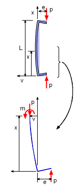
At the length x where the column is cut, there is a moment (m) and an axial load (P). For the column to be in equilibrium, the sum of all moments should be zero.
![\[ \sum M=0 \]](https://punchlistzero.com/wp-content/ql-cache/quicklatex.com-ec0f782718758f31a147c754f85ccdad_l3.png "Rendered by QuickLaTeX.com")
![\[ m+P\left ( e+v \right ) \]](https://punchlistzero.com/wp-content/ql-cache/quicklatex.com-182672ec08ed2055e7df4b354bc3f02f_l3.png "Rendered by QuickLaTeX.com")
From physics, the bending moment in the column is modeled as follows:
![\[ EI\frac{d^{2}v}{dx^{2}}+Pv=-Pe \]](https://punchlistzero.com/wp-content/ql-cache/quicklatex.com-0d9bedd9c84044ff76ed2b02264770fd_l3.png "Rendered by QuickLaTeX.com")
Using a classical differential equation and boundary conditions where x is 0 and L, the deflection equation for the column as a function of x is:
![\[ v_{x}=e\left [ \tan \frac{kL}{2}\left ( sinkx \right )+\cos kx +1\right ] \]](https://punchlistzero.com/wp-content/ql-cache/quicklatex.com-d628d05571a7012bfc5502d7970e710f_l3.png "Rendered by QuickLaTeX.com")
![\[ where\cdots K=\sqrt{\frac{P}{EI}} \]](https://punchlistzero.com/wp-content/ql-cache/quicklatex.com-a752c1ebd43cb85290ea965f21672a10_l3.png "Rendered by QuickLaTeX.com")
When a column is under an eccentric load with these end conditions, the maximum deflection occurs at the middle where x = L/2. Thus, the maximum deflection is:
![\[ v_{max}=e\left [ \sec \frac{kL}{2} -1\right ] \]](https://punchlistzero.com/wp-content/ql-cache/quicklatex.com-e95ca512b82bd25d630ae9d2d9ada340_l3.png "Rendered by QuickLaTeX.com")
Column Stress
As earlier sections highlight, the resultant stress on the column will be a combination of direct stress and bending stress. Because the direct stress is constant and only the bending stress varies along the column, the maximum resultant stress (σmax) will occur where bending is maximum, which is vmax and Mmax. So, the expression for this maximum resultant stress is as follows:
![\[ \sigma _{max}=\frac{P}{A}+\frac{M_{max}c}{I} \]](https://punchlistzero.com/wp-content/ql-cache/quicklatex.com-df8084df422f8a0e2ad38ebc357305e9_l3.png "Rendered by QuickLaTeX.com")
![\[ =\frac{P}{A}+\frac{P\left ( e+v_{max} \right )c}{I} \]](https://punchlistzero.com/wp-content/ql-cache/quicklatex.com-09e26e6bdd89f9f66b751bbdd06d89b5_l3.png "Rendered by QuickLaTeX.com")
![\[ =\frac{P}{A}+\frac{Pce}{I}\left ( \sec \frac{kL}{2} -1\right ) \]](https://punchlistzero.com/wp-content/ql-cache/quicklatex.com-a04257039640771243444291004adc12_l3.png "Rendered by QuickLaTeX.com")
Eccentric Load on a Beam
When a simply supported beam is under an eccentric load, it also experiences an uneven distribution of stress. As a result, its bending and deflection behavior differ from beams under centric loads.
Bending Moment on a Beam
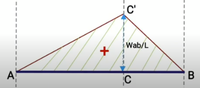
The figure below shows an eccentric load (W) acting at point C on a beam that is simply supported at ends A and B, with reactions RA and RB respectively.
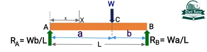
Establishing the bending moment relationship for the beam involves assessing the moments about two separate sections. First is between points A and C, while the second is between points C and B. So, taking the bending moment (Mx) at x from end A in the first section gives the following expression.
![\[ M_{x}=\frac{Wbx}{L} \]](https://punchlistzero.com/wp-content/ql-cache/quicklatex.com-eeaa4442d48938ca7667aa9dee5b2bbc_l3.png "Rendered by QuickLaTeX.com")
Using the expression above, the bending moment for the first section will be 0 at A where x is 0, but at C where x is a, the bending moment is given as:
![\[ M_{x}=\frac{Wba}{L} \]](https://punchlistzero.com/wp-content/ql-cache/quicklatex.com-1d4ea3d85ee919d793ab3f6bbd9987c3_l3.png "Rendered by QuickLaTeX.com")
This shows the bending moment varies by a straight-line law with a value of 0 at A, and Wba/L at C.
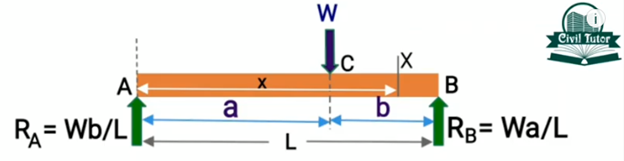
Next, take moments about the second section of the beam between C and B, at x from A, to produce the following expression:
![\[ M_{x}=R_{A}x-W\left ( x-a \right )=\frac{Wbx}{L}-Wx+Wa \]](https://punchlistzero.com/wp-content/ql-cache/quicklatex.com-d4d9cb46c21a7baaad8b6d492d1dd768_l3.png "Rendered by QuickLaTeX.com")
At x = a
While at x = L
![\[ M_{x}=W\left ( b+a \right )-WL=0 \]](https://punchlistzero.com/wp-content/ql-cache/quicklatex.com-cc1e011c425ba7bc46a6a437bc4a2980_l3.png "Rendered by QuickLaTeX.com")
As in the previous section’s bending moment analysis, the moment varies linearly with a value of 0 at B. Then increases till it attains its maximum at C where the eccentric load is acting, as the bending moment diagram below shows.
Deflection of a Beam
The deflection of a beam due to an eccentric load can be determined from the general equation for the bending moment on a beam.
![\[ M=EI\frac{d^{2}y}{dx^{2}} \]](https://punchlistzero.com/wp-content/ql-cache/quicklatex.com-028b841b47696c0177621f5c73aefe3b_l3.png "Rendered by QuickLaTeX.com")
In this equation, EI represents the flexural rigidity of the beam, x is the lateral distance, and y is the vertical deflection. Equating this general expression to the bending moment equation from the previous section gives the expression below:
![\[ EI\frac{d^{2}y}{dx^{2}}=\frac{Wbx}{L}-W\left ( x-a \right ) \]](https://punchlistzero.com/wp-content/ql-cache/quicklatex.com-1cbd4a641f6a60a0cc5ed04dda657f2e_l3.png "Rendered by QuickLaTeX.com")
Integrating this equation twice and solving it to obtain the constants using the boundary conditions gives the expression for finding the deflection (y) at any point of the beam:
![\[ EIy=\frac{Wbx^{3}}{6L}-\frac{W\left ( x-a \right )^{3}}{6}+\frac{Wbx\left ( b^{2}-L^{2} \right )}{6} \]](https://punchlistzero.com/wp-content/ql-cache/quicklatex.com-8474e0be7454fca2c217696ad4b34e0d_l3.png "Rendered by QuickLaTeX.com")
Because of the loading is not eccentric, the maximum deflection will not be at the center of the beam. Rather, it will be at the point along the x-axis where the slope (dy/dx) is 0.
![\[ @\frac{dy}{dx}=0 \]](https://punchlistzero.com/wp-content/ql-cache/quicklatex.com-54b5360cd16eaaee44888c0dbce2b387_l3.png "Rendered by QuickLaTeX.com")
![\[ x=\sqrt{\frac{L^{2}-b^{2}}{3}} \]](https://punchlistzero.com/wp-content/ql-cache/quicklatex.com-ae26db1533eb375323886ca44cea02f3_l3.png "Rendered by QuickLaTeX.com")
Replacing the value for x in the deflection equation gives the expression for the maximum deflection on a beam with an eccentric load.
![\[ y_{max}=\frac{Pb\left ( L^{2}-b^{2} \right )^{\frac{3}{2}}}{9EIL\sqrt{3}} \]](https://punchlistzero.com/wp-content/ql-cache/quicklatex.com-adfbd18b48429a9dcf9025c01617897e_l3.png "Rendered by QuickLaTeX.com")
Impact of Eccentric Load on Footings
Generally, a foundation serves to distribute loads of a structure to the underlying soil. This is because the soil cannot bear concentrated loads. Correspondingly, the soil exerts a reaction pressure to the foundation at the contact surface between them. But a variety of reasons such as earthquakes and wind loading can lead to eccentric loading on the soil. When this occurs, there will be a bending moment on the connection of the footing and the column as the figure below shows.
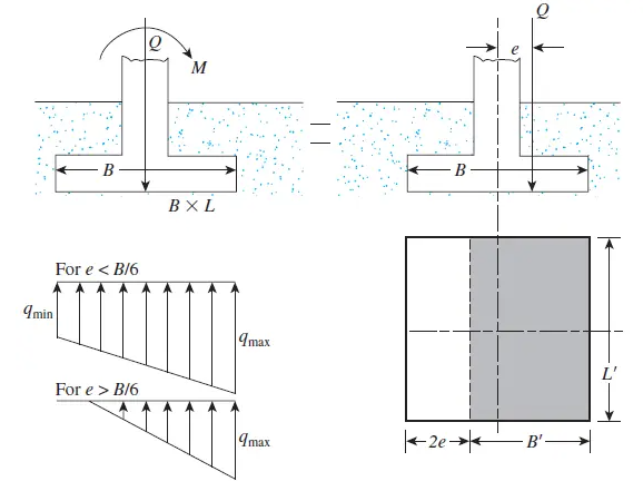
Because of this bending moment, there is an uneven distribution of contact pressure at the foundation-soil interface. This contact pressure (q) is a function of the direct stress and bending stress on the footing, with its minimum and maximum values as follows:
![\[ q_{min}=\frac{Q}{BL}\left ( 1-\frac{6e}{B} \right ) \]](https://punchlistzero.com/wp-content/ql-cache/quicklatex.com-f00f033100b8beb7656c8cbcb62acc10_l3.png "Rendered by QuickLaTeX.com")
![\[ q_{max}=\frac{Q}{BL}\left ( 1+\frac{6e}{B} \right ) \]](https://punchlistzero.com/wp-content/ql-cache/quicklatex.com-6996a279ee9bff30d66c3012c28b3d9f_l3.png "Rendered by QuickLaTeX.com")
During the foundation design, a comparison between the maximum contact pressure value and that of the soil’s bearing capacity reveals their compatibility.