A chamfer is a slope at the edge of a part and a chamfer callout refers to how to dimension chamfers on drawings. Generally, chamfers serve to remove burs and facilitate the assembly of close-fitting parts. In this article, you will learn the proper way to do a chamfer callout, as well as how to do the callout in popular software programs.
Proper Chamfer Callout
A proper chamfer callout refers to the appropriate way of specifying a chamfer feature. This is critical when dimensioning drawings, especially for the tolerance of parts that make up an assembly. Although there are a variety of ways to go about this, there are common approaches, which are as follows:
- Using the chamfer’s length and angle (e.g. 0.09” x 45°) as per ASME Y14.5M.
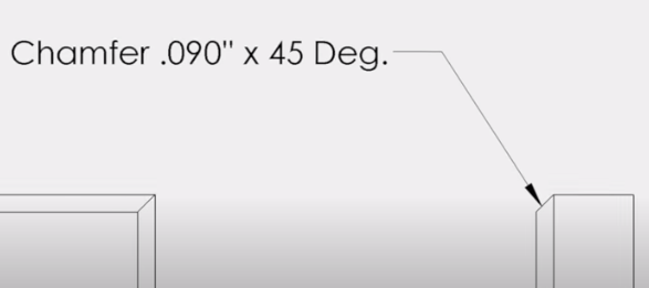
- Also, another way of specifying it is by using its horizontal and vertical length (e.g. 0.09” x 0.09”). Or, in other words, specify the chafer dimensions via the length of its legs. When this approach is in use and both dimensions are the same, then the angle of the chamfer is automatically 45°.
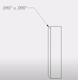
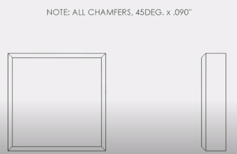
- The two previous approaches are for labeling a specific chamfer feature. But if all features in a drawing are the same, then a general note provides the appropriate information.
Chamfer Callout on Popular Software Programs
Because chamfers are a mainstay in several parts and structures, the option to create the feature is available in a host of design software. However, the approach to executing the callout varies depending on the platform.
Chamfering in AutoCAD
AutoCAD is one of the leading design software in the engineering industry. Generally, there are two methods of carrying out a chamfer callout on this platform. One is specifying the length of the two legs of the chamfer. The other requires specifying one length and an angle.
Specifying Two Legs
Below are the steps of a chamfer callout using its horizontal and vertical dimensions.
- After drawing the part in question, select the chamfer icon from the fillet drop-down menu.
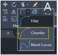
- When the command line opens, type “Distance” or “D”, and press “Enter”.
- Specify the first distance (first leg) value and press “Enter”.
- Then, specify the second distance (second leg) value and press “Enter”.
- Click on the first line and second line, which should correspond to the first distance and second distance respectively.
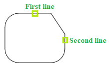
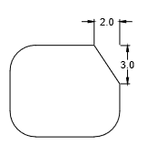
- This creates a chamfer at the corner of the two lines. For example, the figure below shows how it will appear if the first and second distances are 2.0 and 3.0 respectively.
Specifying One Length and the Angle
To create a chamfer in AutoCAD by specifying the angle, the steps are as follows:
- As in the previous method, select the chamfer icon from the fillet drop-down menu.
- Instead of typing “Distance” or “D” as before, enter “Angle” or “A” in the command line.
- Then, enter the length of the chamfer on the first line, and the angle.
- Subsequently, select the first and the second line to complete the chamfer callout.
Chamfering in Fusion 360
Fusion 360 is a cloud-native 3D modeling software platform for product designing and manufacturing. A chamfer callout on this platform is straightforward with the steps as follows:
- After drawing the part, from the menu bar select Design > Solid > Modify > Chamfer. This opens the chamfer dialog box.
- Then select the edges, features, or faces to chamfer.
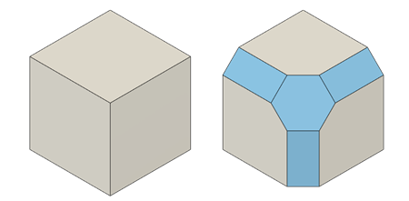
- From the chamfer dialog box, select the chamfer type, of which there are three options in Fusion 360. The first is “Equal Distance”, which creates chamfers with the same dimension for each leg. Next is “Two Distance” which gives the option of inputting different dimensions for each leg. Then “Distance and Angle”, which allows the user to input a single distance and angle for the chamfer.
- Next, enter the dimension values according to the chamfer type selection.
- Finally, chose the corner type for the chamfer of which Fusion 360 offers three options. One is “Chamfer”, which creates a chamfer that joins beveled edges at the corner. Another is “Miter” which merges bevel edges into a mitered corner point. The third option is “Blend” which blends bevel edges into the adjacent faces, creating a smooth transition. After selecting the corner type, click “OK” to close the dialog box and complete the chamfer callout.
Chamfering in Solidworks
Solidworks, one of the leading solid modeling computer-aided design applications, also offers the option of chamfering. Moreover, the procedure for a chamfer callout on this platform is as follows:
- From the Dimensions/Relations toolbar, click on “Chamfer Dimension”. Or select Tools > Dimensions > Chamfer.
- Subsequently, select the edge to the chamfered and one of the lead-in edges, before clicking on the area where the dimension will be placed.
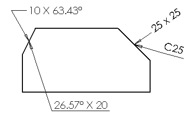
- To create the chamfer, enter the chamfer dimensions in accordance with the option of choice. Note, in Solidworks, chamfer dimensions can be in a variety of ways such as length × angle, angle × length, length × length, or alphanumeric codes. So, the default method should be set before commencing the chamfer callout by clicking Tools > Options > Document Properties > Dimensions > Chamfer.
