Etukudo
An edge break is a common practice when fabricating a component. Moreover, it reduces the sharpness of the edge of a component by material removal. In this article, you will learn more about the edge break, how to make it, review its symbol, and the measurement of an edge break.
More about Edge Break
Machined components usually have sharp or burred edges and corners after fabrication. This creates a safety concern during handling. Also, the presence of burrs is not visually appealing on manufactured parts. Thus, the need to create an edge break on most components exists. Generally, this is achieved by rounding off corners, machining a flat edge transition, or creating a chamfer to reduce the sharpness. As a result, the performance of the component improves, as well as safety and longevity.
The following are applications where edge breaking improves performance, safety, and longevity:
- A radiused or chamfered edge greatly reduces the possibility of fracture when subject to high stresses or load. In addition, it helps parts of an assembly fit properly.
- Also, chamfering of fasteners prevent them from protruding from casings and shafts.
- In terms of performance, having tight edge break tolerances ensure proper aerodynamic response in components such as turbine nozzles and blades.
- Edge breaking of parts with which people interface reduces the risk of injuries from burrs and sharp edges.
How to Make an Edge Break
The way to make an edge break depends on the purpose of the break and the type of material in use. If the intention is just to remove sharp edges for safe handling, then handheld abrasives such as sandpaper and file usually suffice. Otherwise, in the case where the dimension of the break is critical to the part’s functionality, more sophisticated methods are deployed.
Edge Breaking on Wood
Wood is soft in comparison to other engineering materials. Thus, the easiest way of creating an edge break on a wooden component is by using a 180-grit fine sandpaper. Another option is to use a block plane to chamfer the edge, then soften it with light sanding.
Edge Breaking on Glass
Glass is brittle and more difficult to work with in comparison to wood. Some common tools for edge breaking of glass are:
- Grinding wheel.
- Diamond file.
- Diamond wheel with rotary tool.
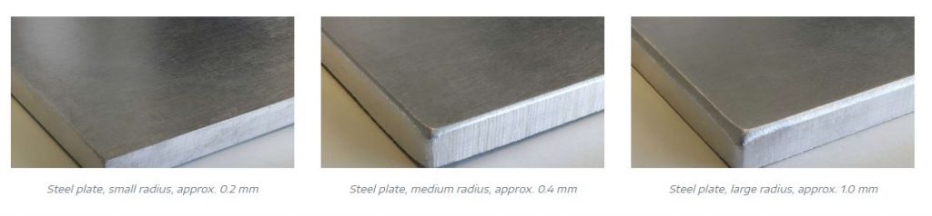
Edge Breaking on Metal

Due to the attributes of steel as well as other metals, they are the most common engineering material. In addition, their durability allows for a wider range of methods to create an edge break including:
- Using a chamfer deburring tool to remove burrs from the edge of metal parts.
- The use of sandpaper or file to smoothen out edges.
- Also, utilizing a grinding wheel or rotary tool such as a Dremel.
Edge Break Symbol
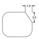
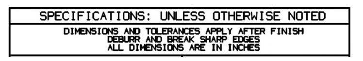
On an engineering blueprint, there is no geometric dimensioning and tolerancing symbol for an edge break. Rather, their callouts are specified directly on the drawing to reference a certain surface like in the figure below.
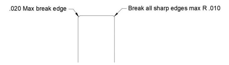
Alternatively, it could be stated as a note in a general tolerance block like in the diagram below.
Generally, an edge break callout is identical to that of a radius. But in the case of a chamfer callout there is a difference in their tolerancing. Because chamfer tolerancing is associated with the angle, therefore placing tighter constraints on the feature.
Measurement of an Edge Break
Most times, an edge break is for safety and aesthetic purposes, so its measurement is not important. But if it is a critical feature – such that it is needed for a part to function properly – it is necessary to specify its dimension. In addition, it is important to be able to verify this dimension easily and quickly. For example, in the automotive and aviation industries, a part could have several callouts. Thus, it makes measurements time-consuming and challenging.
Generally, checking the size of an edge break is the same as with chamfers and radiuses. Traditional methods often deploy a visual check using optical comparators or eye loupes with reticles. Another visual method involves using a paper corner gauge to compare the part. All these are 2D approaches are prone to large errors due to variability in both position and angle of measurement.
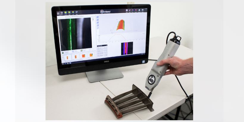
3D methods that utilize laser-based gauge guns and accompanying software provide more optimal solutions. They offer accuracy, repeatability, and speed in taking measurements.