Etukudo
Power dissipation refers to the process by which an electrical or electronic device loses or wastes energy via heat production while performing its primary action. Moreover, it is important to consider the dissipation value from various components in a system as failure can occur due to excessive heat. In this article, you’ll learn more about the process of power dissipation, the power dissipation formula, and its application to various circuitry and components.
Process of Power Dissipation
When applying voltage across an electrical component, it is energized as current flows through it. So, the rate at which this component is energized is the power, which is common knowledge in engineering. Depending on the purpose the component is serving, it converts this power into light, motion, heat, or any other form of energy. However, because of the inefficiencies within the system, a certain amount of energy is often given off as heat. It is this component that is referred to in power dissipation. Although the design of most circuits aims to minimize power dissipation, in some cases, it is desirable. Nevertheless, whether desirable or not, it is necessary to properly estimate the level of power dissipation in any circuit or component.
Power Dissipation Formula
Generally, the expression for power dissipation for an element or component in a circuit is:
![\[ P=I\times V \]](https://punchlistzero.com/wp-content/ql-cache/quicklatex.com-d8fe1aea8d0e9bc607b0173cb1e6ee37_l3.png "Rendered by QuickLaTeX.com")
In the formula, P refers to the power dissipation from the element, I is the current that flows through it, while V is the voltage drop across it.
Application to Electrical/Electronic Components
The process and impact of power dissipation vary depending on the electrical circuitry and component. Moreover, in applications where it is not desirable, the design of circuits and components aims at evading it. For applications where the power dissipation results in useful work, components that increase its occurrence are used.
Power Dissipation in Resistors
In resistors, it is safe to say that power dissipation is a naturally occurring phenomenon. Because all electrical energy delivered to these elements are converted to heat. As a result, applications that need heat often use a variety of resistors. For example, Nichrome is a unique element whose features include stability at high temperatures, resistance to oxidation, and generating significant heat when current passes through. Thus, it is a popular choice for electric heaters. Also, the tungsten element in incandescent bulbs is another resistor renowned for its high level of power dissipation. Generally, it uses about 5% of its energy for generating visible light, while the remainder produces heat. However, if the power delivery to a resistor is at a higher rate than what it dissipates, its temperature continually increases until failure occurs. Therefore, resistors have a maximum power dissipation specification.
So, if the value of either the current or voltage drop is not available, then performing a substitution from Ohm’s law enables the power loss to be represented in variable forms using the resistance, R, of the element.
![\[ P=\frac{V^{2}}{R} \]](https://punchlistzero.com/wp-content/ql-cache/quicklatex.com-4e0a2565a78371279b51d66d041ae8cc_l3.png "Rendered by QuickLaTeX.com")
![\[OR\]](https://punchlistzero.com/wp-content/ql-cache/quicklatex.com-eb6ce750ee55d4ffbe1a9612b48a6a89_l3.png "Rendered by QuickLaTeX.com")
![\[ P=I^{2}R \]](https://punchlistzero.com/wp-content/ql-cache/quicklatex.com-b950cdcbf78208bcdd0f7fbed57e3ad4_l3.png "Rendered by QuickLaTeX.com")
Inductors
For an ac circuit, the power dissipation (Pac) is a function of the RMS values of voltage (Vrms) and current (Irms), as well as the power factor (cosφ).
![\[ P_{ac}=V_{rms}\times I_{rms}\cos \varphi \]](https://punchlistzero.com/wp-content/ql-cache/quicklatex.com-7b334d798d750165a47c113a78de2077_l3.png "Rendered by QuickLaTeX.com")
In turn, the power factor is a function of the resistive component (R) of the circuit, and its relationship to the total impedance (Z) in the circuit.
![\[ \cos \varphi =\frac{R}{Z} \]](https://punchlistzero.com/wp-content/ql-cache/quicklatex.com-7105fca7cd74e9b0f173c002c8200744_l3.png "Rendered by QuickLaTeX.com")
For a purely inductive circuit, there is no resistance (R = 0). As a result, there will be no power loss. However, this is not the case in practice, with the total power dissipation (Ploss) consisting of the core loss (Pcore), and wire losses due to ac resistance (Pac) and dc resistance (Pdc).
![\[ P_{loss}=P_{core}+P_{acr}+P_{dcr} \]](https://punchlistzero.com/wp-content/ql-cache/quicklatex.com-04031e85eb080c1c1c92dd83f99e5459_l3.png "Rendered by QuickLaTeX.com")
Core Loss
This refers to power dissipation due to hysteresis and eddy currents in the armature of the inductor. Moreover, its expression varies depending on the core material. Also, the repeatability of the results when checking for this value depends on the test frequency (f) and its exponent (x). For example, for ferrite cores, the constant for the core material (K1), peak flux density (B), flux density exponent (y), as well as the effective core volume (Ve) are influencing variables on power loss.
![\[ P_{core}=K_{1}\times f^{x}\times B^{y}\times V_{e} \]](https://punchlistzero.com/wp-content/ql-cache/quicklatex.com-ba78e09a5b8cc00c16a40683d4de603a_l3.png "Rendered by QuickLaTeX.com")
DC Resistance
The component of power loss due to dc resistance (Rdc) is easy to estimate as follows:
![\[ P_{dcr}=I_{rms}^{2}\times R_{dc} \]](https://punchlistzero.com/wp-content/ql-cache/quicklatex.com-2bd850ff32a34e662e61adc8889ca0a5_l3.png "Rendered by QuickLaTeX.com")
AC Resistance
Similarly, estimating the power dissipation due to ac resistance is straightforward, using the RMS value of the peak-peak ripple current across the inductor as follows:
![\[ P_{acr}=I_{rms}^{2}\times R_{ac} \]](https://punchlistzero.com/wp-content/ql-cache/quicklatex.com-cb294e31f10fd8d6c085a39793cf4736_l3.png "Rendered by QuickLaTeX.com")
Diode
Generally, the design of diodes is such that current flows in just one direction. Thus, acting as an electrical check valve. Often, they serve as rectifiers to convert ac power to dc, with insignificant resistance at one end, and high resistance at the other end. So, power dissipation from this component is basically due to resistance. However, its value varies depending on the direction of current flow.
MOSFET
Metal-oxide-semiconductor field-effect transistor (MOSFET) is a type of transistor that amplifies or switches electronic signals. The total power dissipation (PDtotal) from these transistors consists of the resistive component (PDresistive) and the switching component (PDswitching).
![\[ PD_{total}=PD_{resistive}+PD_{switching} \]](https://punchlistzero.com/wp-content/ql-cache/quicklatex.com-7d1d1748771cb7907a30e9d26274c1d2_l3.png "Rendered by QuickLaTeX.com")
Resistive Component
The resistive component of the total power dissipation of a MOSFET is a function of its drain-source resistance (RDSON) when turning on. In turn, this drain-source resistance is a function of the junction temperature (TJ). Moreover, this resistive component is at its maximum when the junction temperature is at its maximum too. Also, this resistive power dissipation (PDresistive) is a function of the current passing the drain-source resistance (IR), and the input and output voltages (Vin and Vout).
![\[ PD_{resistive}=\left [ I_{R}^{2}\times R_{DSON\left ( max \right )} \right ]\left ( \frac{V_{out}}{V_{in}} \right ) \]](https://punchlistzero.com/wp-content/ql-cache/quicklatex.com-0ce404fcd9754ee86c8b1766ca889bc4_l3.png "Rendered by QuickLaTeX.com")
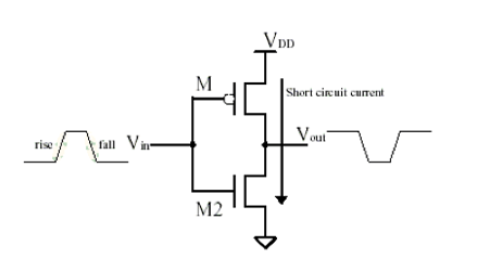
Switching Component
High-speed switching is one of the activities that improves efficiency in amplifiers. But power is dissipated during the transition period as the diagram below shows.
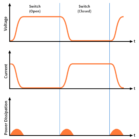
Calculating the precise value of the power loss due to switching is challenging, due to several parameters influencing it. Also, these parameters themselves are difficult to determine. In any case, the power dissipation component due to switching (PDswitching) is a function of the reverse-transfer capacitance (Crss), the switching frequency (fsw), and the gate-driver’s sink/source current (Igate). So, to reduce this switching component, it is advisable for designers to keep the switching time as short as possible.
![\[ PD_{switching}=\frac{\left ( C_{rss}\times V_{in}^{2}\times f_{sw}\times I_{R} \right )}{I_{gate}} \]](https://punchlistzero.com/wp-content/ql-cache/quicklatex.com-abdf6ee3c4b3f418bd90525c727fe661_l3.png "Rendered by QuickLaTeX.com")
CMOS
The total power dissipation (Pt) in a CMOS (complementary metal-oxide-semiconductor) circuit consists of three components: static power dissipation (Pst), dynamic power dissipation (Pdyn), and short-circuit power dissipation (Psc).
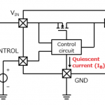
Static Power Dissipation
When a CMOS circuit is in an idle state, there remains some level of power loss. This is due to the leakage current flowing across the internal reverse-biased pn-junction.
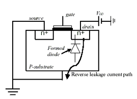
Another source of leakage current is the sub-threshold current resulting from current diffusion. Moreover, this occurs between the source and drain region when the transistor is in weak inversion. A product of the leakage current (Ileak) in the circuit and the voltage (VDD) across, produces the static power dissipation (Pst).
![\[ P_{st}=V_{DD}\times I_{leak} \]](https://punchlistzero.com/wp-content/ql-cache/quicklatex.com-4204cc4cccd5442a861a1ec0e5bbd00e_l3.png "Rendered by QuickLaTeX.com")
Dynamic Power Dissipation
This refers to power loss that occurs while charging and discharging of capacitance. Moreover, the loss is a function of the total output node capacitance (CL), the supply voltage (VDD) to the capacitance, operating frequency (f), and the transition activity factor (a).
![\[ P_{dyn}=C_{L}\times V_{DD}^{2}\times f\times a \]](https://punchlistzero.com/wp-content/ql-cache/quicklatex.com-c1acabf3dab3ea636f26b04175873725_l3.png "Rendered by QuickLaTeX.com")
Short-circuit Power Dissipation
During the switching of transistors, there is a direct path current flowing from the power supply to the ground. This results in short-circuit power dissipation (Psc) that depends on the supply voltage (VDD), short circuit current (Isc) and short circuit time (t).
VLSI
VLSI (very large-scale integration) refers to an integrated circuit coming about by combining millions of MOS (metal-oxide semiconductor) transistors into a single chip. This enables the development of complex telecommunication and semiconductor technologies. Like the CMOS, the total power loss of VLSI consists of the static, dynamic, and short circuit components. Also, the formula for obtaining these components remain the same as in the previous section.