Etukudo
A selector switch is a mechanical control device that enables switching between a minimum of two electrical circuits. It is common in applications where there is more than one control option, but only one is to be active per time. In this article, we will review how a selector switch works, and the selector switch diagram for 2, 3, and 4-position switches.
How a Selector Switch Works
The basic function of a selector switch is to provide flexible controls with minimal space. It usually achieves this by operating a knob, which rotates to specific positions to connect or disconnect various circuits. In some applications, the switching is automatic or remote, but the principle of operation remains the same. Basic components that make up a selector switch include:
- Operator/Actuator: This part of the switch moves to either open or close a circuit. Manual selector switches usually come in the form of a knob. However, some recent versions utilize buttons, which are more popular in automatic and remote switches.
- Contact Block: This component encapsulates the contactors of each circuit in the system. Generally, the gap between the actuator and contactor is 0.5mm when a circuit is not active. Whereas for high accuracy and high durability applications, the gap is much smaller around 0.25mm. However, such a small gap will make the system prone to arcing if there is significant vibration or shock. To make the system resistant to these, the contact gap is typically 1 and 1.8mm in systems that experience vibration.
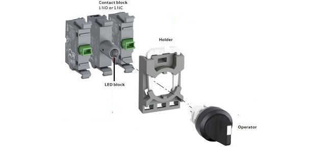
- LED Block: The LED block has indicator lighting that shows the position of the actuator.
- Casing: Houses all internal components of the switch, so it is durable and comes in a variety of shapes. Predominant materials are plastic and metals. Also come in a variety of IP or NEC ratings depending on its operating environment.
Categorization of selector switches depends on the number of circuits it is connecting. Moreover, the most common options in the industry are 2, 3, and 4-position switches.
2-Position Selector Switch
This type of selector serves in switching between two circuits. It also goes by the names 2-way switch and single-pole double throw switch. Typically, they serve in on-off applications such as the following:
- Lighting: 2-position selector switches are popular in simple lighting applications for switching on or off a lighting point.
- Motor Control: This can serve in switching on and off a motor, as well as in changing the direction of motor rotation in reversible motors.
- Temperature Control: 2-way switching is useful in controlling the temperature in a room by changing between two different cooling or heating sources.
- Audio/Video Routing: When there are two different audio/video sources and one output, a 2-position selector is effective in switching between them.
3-Position Selector Switch
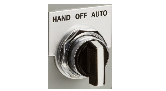
A 3-position selector goes a step further by enabling switching between three different circuits. So, this type of switch has three position states, which often go by the name ‘Hand – Off – Auto’ (HOA). The HOA name is largely because of its frequent use in motors that have the auto start function. When utilized on a motor starter, the ‘hand’ position indicates a manual operation of the motor. The ‘Auto’ position allows the automatic starting of the motor using a means such as a PLC or sensor. Finally, the ‘Off’ position is for shutting down the system. This selector is similar to the 2-position switch but enables input from two different circuits where there is a requirement to have both circuits normally open.
Although the HOA arrangement is quite common for 3-position selector switches, there is a downside to it, especially when on large motors. If the selector is on ‘Hand’ with the motor running and needs to switch to ‘Auto’, the starter will have to drop off before reenergizing as it goes through the ‘Off’ position. This is why some motors utilize the ‘Off – Auto – Hand’ switch instead. However, having the ‘Off’ position at the center is desirable in certain applications for safety reasons, as it enables a quick shutdown.
3-Position Selector Switch Diagram
This section highlights how a 3-position selector switch works in a lighting application, using a diagram. In this example, the selector switch serves to control two different lighting points where only one light is to be on per time. As the figure below shows, the switch has 1-0-2 positions which are akin to the ‘Hand-Off-Auto’ positions. Also, the switch is in the ‘Off’ position, so neither of the lights are on.
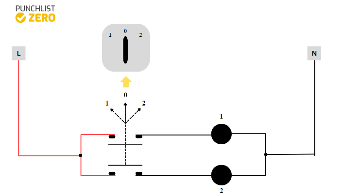
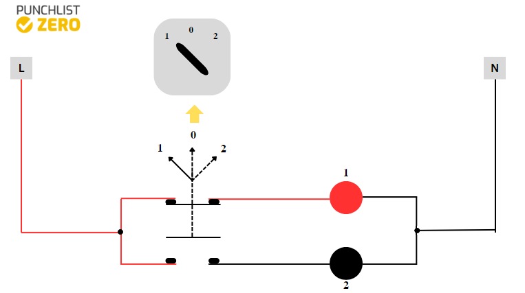
In this ‘off’ position, none of the contactors in either light position is connected. To put on the light in position 1, an operator turns the knob accordingly, thus resulting in the connection of the contactors on line 1.
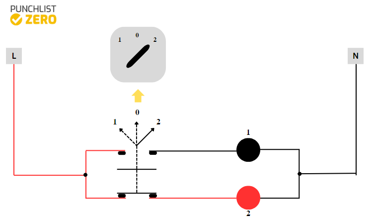
Similarly, the light along line 2 can become active by turning the selector to the corresponding position, as the figure below highlights.
4-Position Selector Switch
The 4-position selector switch is quite similar to its 3-position counterpart. In that, it enables switching between multiple circuits – in this case, three – as well as an ‘off’ position. Thus, the three circuits can meet the requirements of being normally open at the same time. This type of switch is common in both residential and industrial applications, where it serves as fan regulators, blender speed regulators, switching between motors, etc.