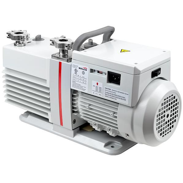
Electric motors have a broad range of applications, from children’s toys to huge industrial fans. Electric motors are known for their versatility and ability to supply power in numerous applications. In this article, you will learn about the design and construction of industrial electric motors.
An electric motor is energized by an electric source. Electricity induces a magnetic flux on the motor’s stator. The stator interacts with the rotor and drives the motor’s shaft. The spinning shaft allows power transfer to a load. Electric motor efficiencies are typically around 90%, which is much higher than other forms of power such as an internal combustion engine.
Most electric motors used in industrial applications will be alternating current (A.C.). The reason being is that A.C. power is the readily available power source of plants and facilities. Further, there are two primary motor A.C. motor designs: synchronous and induction. Synchronous motors feature direct contact between the stator and the rotor. Induction motors are far more common and has no direction connection between the stator and rotator.
As such, we will first approach motor design and construction from an A.C. induction motor point of view and then discuss applications and characteristics of its direct current (D.C.) cousin.
Motor Design and Construction
Electrical Design
In a departure from most industrial applications, design begins with specifying the electrical design. The electrical design specifies the expected rotation speed of the motors, voltage type, number of leads, efficiency, and other attributes of the motor.
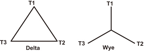
One of the considerations is how the leads are connected. There are two primary options: delta and wye. Delta connections generally have higher reliability as if one of the three primary windings fails, the secondary will still produce full voltage on all three phases. The Wye connection can provide multiple voltages without the need for additional transformers. Additionally, depending on motor voltage, either the Wye or Delta connection will result in larger physical wires.
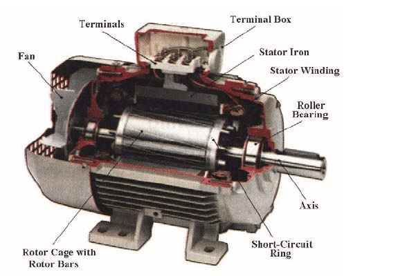
Shaft-Rotor Assembly
In electric motors, a shaft must be carefully designed to avoid harmonic frequency resonance with the input frequency (50hz or 60hz) or a multiple (e.g. 2x, 3x) of that frequency. Shaft material is typically a mild steel, although an alloy steel will be used if the application requires it. The rotor is typically made of thin metal laminations that are fit together and press-fit onto the shaft.
Bearings
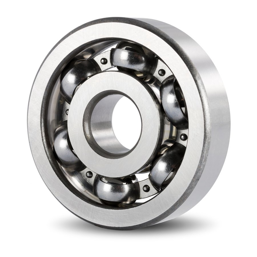
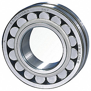
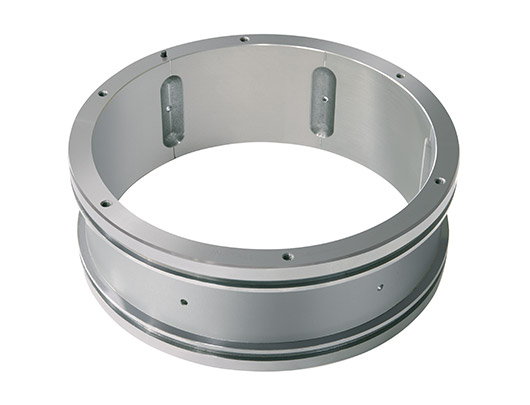
The shaft rests on the motor frame via bearings. Bearings minimize friction, center the rotor shaft assembly, and dampen the force of the motor’s load. In industrial applications, ball bearings are standard. Roller bearings are able to take more force due their elongated design and uniform loading. Sleeve bearings are frequently specified for heavy-duty applications as no mechanical parts are actually in contact with each other. Rather, the sleeve is pressurized with a lubricant on which the shaft rides.
Stator Assembly
The stator assembly is made of thin laminations that are stacked loose, bonded or welded together. The stator assembly is then fit into the frame. Stack laminations are used instead of a solid piece to reduce induced currents and the associated heat.
Motor Frame
The motor frame must protect the windings, bearings, and other mechanical parts from moisture, chemicals, mechanical damage and abrasion from grit.
The two most common frame types for providing this protection are ODP (Open Drip Proof) and TEFC (Totally Enclosed Fan Cooled). The ODP frame allows air to circulate through the windings via a fan, and prevents the drops of liquid from falling into the motor. The TEFC motor extends motor protection to an external environment. When used in specific applications such as a hazardous area or with no fan, numerous other frame types are used.
Leads
The end of the electric motor where leads are connected and the motor is energized is called the lead end. The opposite end of the motor that has an exposed shaft is called the drive end. On most frame types, a fan is fit onto the shaft on the lead end.
Electric motors have the ability to rotate either counter-clockwise or clockwise, which typically determined from the viewpoint of the shaft end. The motor rotation direction is determined by the connection schema of the leads which was established during the electrical design.
Motor Speed
To understand how speed is determined motors an understanding of poles in critical. The number of poles describes how many magnetic poles are present in one circle of each coil and decides the rotations per minute (RPMs) of the motor.
The number of poles has an inverse relationship with the RPM of the motor as per the formula:
RPM = (F x120)/P
The following values are obtained by using the standard United States value of 60Hz for F:
- RPM for 2p = 3600
- RPM for 4p = 1800
- RPM for 6p =1200
- RPM for 8p = 900
For 50hz countries such as Europe, the default pole speed will be as follows:
- RPM for 2p = 3000
- RPM for 4p = 1500
- RPM for 6p =1000
- RPM for 8p = 900
In real-world applications, all motors will run slightly slower than the pole RPM due to slip. Slip is described as the difference between the synchronous speed of the electric motor magnetic field and the shaft rotating speed. Slip is commonly represented as the ratio between the two quantities. Iyt mainl depends on the parameters of the motor and is given by the formula:
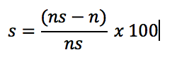
where n is the actual speed and ns is the synchronous speed of the motor.
Directly Energized Applications
The most economical application of an electric motor is the directly energized application. In this application, the motor’s leads are hooked directly to an alternating current power supply. The motor will run at its rated RPMs, which will be the given pole speed (2p, 4p, 6p, 8p) less the slip. A few examples of directly energized applications are: cranes, conveyors, and gear-type pumps.
Variable Speed Applications
When motors are paired with a variable frequency drive (VFD), precise motor control is obtained. Speed is changed by varying the voltage and frequency of the motor’s power supply via the VFD. VFDs may also control ramp-up and ramp-down of the motor during start or stop, respectively.
D.C. Considerations
D.C. motors operate from a direct current. Polarity and slip in D.C. motors does not exist. D.C. motors are characterized as self-excited or separately excited, depending on where the power source exists. If direct current is provided externally, it will be delivered by batteries or A.C to D.C. power converters. The speed of a D.C motor is achieved by the varying of current through an armature winding.
Advantages of a D.C. motor are: higher starting torque, quick starting and stopping capability. D.C. motors can achieve variable speeds without the use of a VFD. This versatility makes them a great fit for small applications, when an A.C. voltage power source is not available, and smooth startup is needed (e.g. car batteries, conveyor systems).
Load Application
An electric motor exists to deliver power to a load. There are two configurations in which an electric motor can do this: direct drive and belt driven.
Direct Drive
In direct-drive motor designs, there are no belts, pulley, and bearings. The motor’s shaft is directly coupled to the load. Direct Drive is usually considered much more efficient and can achieve higher RPM values than belt-driven systems. Direct drive motors are generally considered more robust in most applications as the shaft, and subsequently the motor bearings are not subject to eccentric loads.
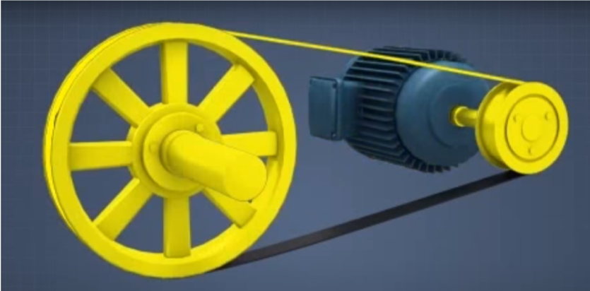
Belt Driven
Belt drives are also referred to as flexible machine elements. A significant amount of shock, as well as vibrations, can be absorbed by such elements. The belt drive transmits power from the motor to the actual load. Example use cases are delivering power to a fan, conveying system, or when a set speed must economically be delivered to a rotating load.
Maintenance and Repair Considerations
Following proper routine maintenance steps is crucial for the long life of a motor.
- Perform an insulation resistance check by measuring the resistance between the windings and the ground of the motor. The resistance should be a high number, typically over 100MΩ.
- A uniform air gap ensures an efficiently operating motor. Motor air gaps can be checked by feeler gauges.
- Proper lubrication is a key factor in the maintenance of the motors and efficient operation.
- Rotor alignment must be checked as well. When rotors are misaligned, the load will try to pull to its magnetic center, causing excessive bearing load.