Etukudo
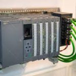
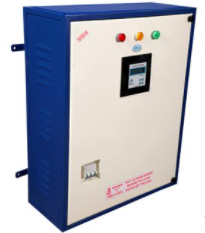
PLC is short for Programmable Logic Controller. PLC cabinet refers to the housing that contains a control system, which automates various industrial processes. In addition, the cabinet protects its components from environmental conditions and avoids unintended interference of users.
In this article, you will learn about the different types of PLC cabinets, their layout, wiring, and components of the control system.
Types of PLC Cabinet
The classification of PLC cabinets varies depending on the area of focus. As such, the classification may occur via the type of module, the nature of mounting, and the type of output.
Classification of PLC Cabinet by Module
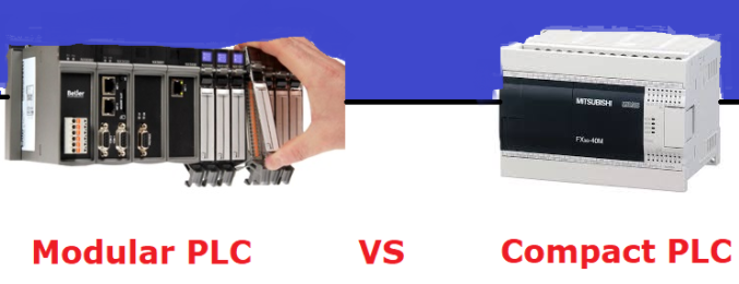
This is the most common way of classifying PLC cabinets and there are two types: compact and modular.
- Compact PLC: This type of PLC cabinet has a fixed number of I/O modules and external I/O cards. Thus, it does not have the capability to expand operation. As a result, the operators and manufacturers need to be in sync about the needs of the project or application before manufacturing is complete.
- Modular PLC: This type offers engineers the flexibility of expansion using modules. Because each I/O component is independent of each other, it is possible to increase their number to meet growing demands.
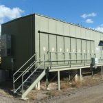
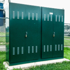
Nature of Mounting
The method by which engineers mount a PLC cabinet serves as another means of classification. They include free-standing, floor-mounted, and wall-mounted. Moreover, the type of mounting for an application largely depends on the working environment. Thus, onerous environmental conditions require more rigid mounting specifications.
Classification of PLC Cabinet by Output
The common types of output for PLC are relay output, transistor output, and TRIAC output. The relay output best suits AC and DC output devices, while transistor output is ideal for switching operations in DC loads. On the other hand, TRIAC output suits switching operations for AC loads.
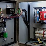
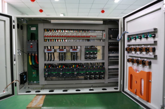
Wiring of PLC Cabinet
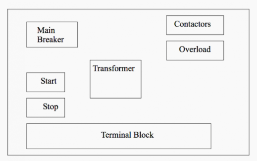
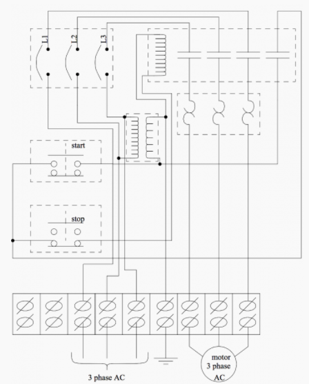
The wiring design of a PLC cabinet is the most intricate aspect of its manufacturing. This design comprises not only power cables and signal lines, but also other devices to ensure safety and efficiency.
- Transformers: Step down AC supply voltages to lower levels for the safety of other devices.
- Terminals: Offer a safe and efficient way of connecting devices.
- Fuses/Circuit Breakers: Ensure the safety of devices by cutting off power if current is excess.
- Grounding: Provides a path for current to flow when there is an electrical fault.
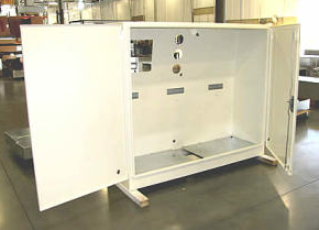
- Enclosure: Prevents accidental contact between equipment and users.
In addition to these devices, the PLC cabinet wiring design has ancillary equipment that includes:
- Hold downs: Secures wire in place.
- Strain reliefs: Prevents the pulling of wires out of their terminals.
- Labels: Provides guidance during troubleshooting.
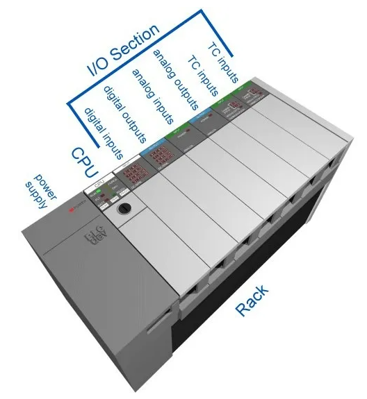
Layout PLC System
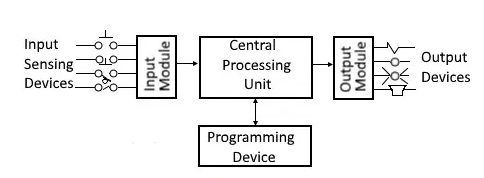
As the function of the PLC cabinet is like that of a computer, so is its layout. Moreover, the cabinet provides a connection interface for the input module, output module, central processing unit, and programming device.
Components of a PLC Cabinet
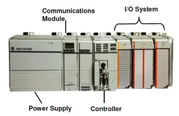
There are several devices in a PLC cabinet. These can be classified into five types of components: power supply module, CPU module, Input/Output Module, communication interface module, and the programmable device.
Power Supply Module
This provides the power requirements for the entire PLC cabinet. Moreover, it converts the available AC power to DC power, which is key for the CPU and I/O modules. In any case, the power supply module does not provide power for the field devices.
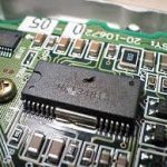
CPU Module
This consists of a central processor, ROM, and RAM memory. Its constituents provide the platform that helps it run its operating system, application programs, and drivers. In addition, it reads data from sensors, processes the data, and sends the appropriate command to the controlling device.
Input and Output Module
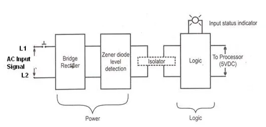
The input and output (I/O) module consists of various devices by which the PLC receives and sends signals. Furthermore, the input devices include start and stop pushbuttons, sensors, and switches. Typical output devices include valves, relays, heaters, etc. The input module performs the following functions:
- Receives AC signal from process devices and converts to DC.
- Prevents the PLC from undergoing signal fluctuations by the aid of an isolator block.
- Sends stable signal to the CPU module.
To perform these functions, designers ensure that the input module has a power section and a logical section, which are electrically isolated from each other. Moreover, designers refer to this process of isolating the power section, typically of copper wires, from the control wiring that constitutes the logical section, as power routing.
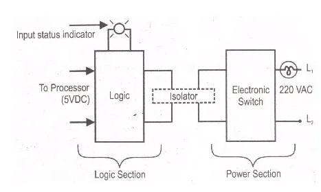
Similarly, the output module works the same way as the input module but in a reverse process. Thus, the logic section comes first before the power section.
Communication Interface Module
Most times, engineers take this module as part of the I/O module, but it is necessary to view it as separate due to its unique function within the PLC cabinet. The communication interface module transfers information between the CPU and the programming device/computer that the operators work with. It uses intelligent I/O modules and control wiring to offer high-speed transfer of information so that operators can know what is happening in real-time at various parts of the PLC system, and to program corresponding instructions.
Programmable Device
Although the programmable device is not within the PLC cabinet, it is an integral part of the system. Typically, the programmable device is a desktop or laptop, which interacts with the system to create, monitor, and edit the PLC program. Moreover, this program is a set of instructions in textual or graphical form, representing the logic that governs the process the PLC is controlling. In practice, the programming languages that professionals deploy are as follows:
- Textual Language: This includes instruction list and structured text.
- Graphical Language: This could be in the form of ladder diagrams, functional block diagrams, or sequential function chart.