Equivalent fluid pressure (EFP) is a simplification of the lateral loading that the soil exerts on an earth-retaining wall. Moreover, the equivalent fluid refers to a hypothetical fluid, having a unit weight that produces pressure against a lateral support of which its value is presumably equal to that the actual soil produces. It is common to express its value in pounds per cubic foot (pcf).
In this article, you will learn the background of EFP, its calculation and table, criteria for its use, and retaining wall design.
Background
The use of EFP stems from a publication of the American Association of State Highway Officials, Standard Specifications for Highway Bridges in the 1950s. The association suggests that all earth retaining structures should have a design capable of withstanding a minimum pressure of 30 pcf. However, this method of analyzing pressures and retaining walls has come under scrutiny over the years. This largely stems from its misuse by engineers when analyzing walls that retain earth with a sloping ground surface. As a result, various scientists and engineers took out time to establish reasonable criteria for the application of the EFP method.
Criteria for Using Equivalent Fluid Pressure
Since EFP is an assumption, there are a range of conditions where applying this approach is valid. Also, there are parameters that are ideal for computing using this method.
Paramaters
Some soil parameters that are ideal for using the equivalent fluid pressure assumption include:
- The heel side active soil pressure.
- The soil passive pressure.
- The heel side soil density.
- The toe side soil density.
Conditions
- The EFP approach is suitable when deformation conditions follow the pattern of linear pressure increase with soil depth. It also applies when it is appropriate to neglect wall friction.
- The EFP method is not applicable to ascending slopes due to some limitations.
Limitations when Applied to Ascending Slopes
- It sometimes does not account for the vertical earth pressure component.
- It is not accurate in predicting the direction of the static earth pressure.
- The EFP approach overestimates the sliding factor of safety, heel bearing pressure, moment demand, and top of wall deflection.
- The EFP underestimates the overturning factor, and toe bearing pressure.
Calculation of Equivalent Fluid Pressure
Calculating the equivalent fluid pressure follows a slightly different approach depending on the type of retaining wall.
Calculating EFP for Cantilever Retaining Walls
For a cantilever retaining wall with a level and sub drain backfill, the equivalent fluid pressure (peq) is a product of the active lateral earth pressure coefficient (ka) and the moist unit weight of the backfill (γb).
![]()
There are two common ways to determine the active lateral earth pressure coefficient. Namely the Rankine theory and the Coulomb theory. Because the EFP approach neglects wall friction, it is more appropriate to follow Rankine’s theory. In addition, this theory expresses the active lateral earth pressure coefficient (ka) for a level back slope as a function of the effective angle of internal friction of the soil in degrees (ϕf).
![]()
Calculating EFP for Restrained Retaining Walls
In the case of restrained retaining walls with a level and sub drain backfill, the equivalent fluid pressure (peq) is a product of the at-rest lateral earth pressure coefficient (k0) and the moist unit weight of the backfill (γb).
![]()
The at-rest pressure coefficient replaces the active coefficient for retaining walls because the wall experiences no lateral movement. Also, for normally consolidated soils and a vertical backed wall, the at-rest lateral earth pressure coefficient (k0) is expressed as a function of the effective angle of internal friction of the soil in degrees (ϕf), and the angle of back slope to the horizontal (β).
![]()
Equivalent Fluid Pressure Table
The essence of the equivalent fluid pressure concept is the quick analysis of soil parameters. As a result, geotechnical engineers can avoid carrying out time-consuming and expensive tests on every soil sample. Despite its limitations, the EFP remains useful in doing preliminary evaluations of the soil. From the values that these examinations produce, engineers can decide if there is a need for more intricate examinations.
Equivalent fluid pressure tables exist to aid engineers in the quick determination of values. The EFP value varies with respect to the soil classification.

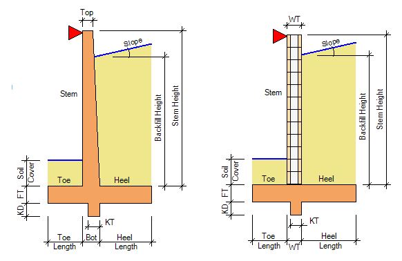
The equivalent fluid pressure also varies depending on the wall batter, backslope geometry, and the retaining wall design method.

From the table above, high EFP values are common with steep back slopes.
Retaining Wall Design
In recent times, geotechnical engineers adopted sophisticated approaches in estimating the lateral load on retaining walls. As a result, despite its usefulness, the equivalent fluid pressure method is on the decrease.

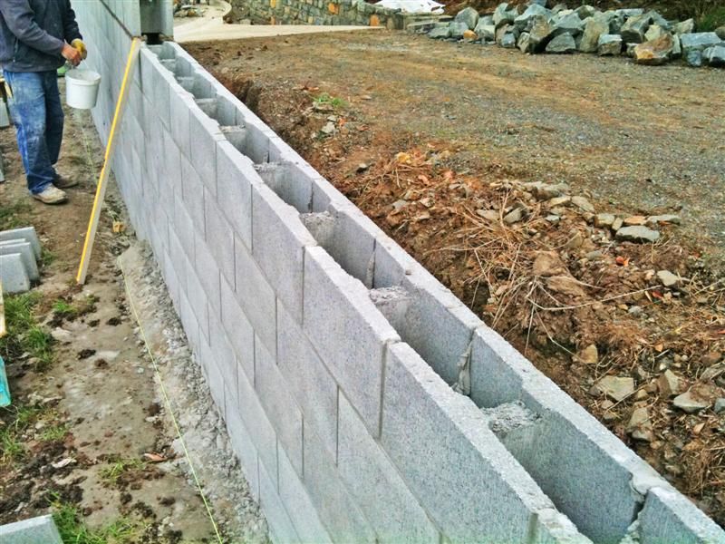
The use of the retaining wall design approach varies depending on the type of wall. Additionally, for concrete masonry retaining walls, there are gravity, cantilever, and segmented retaining walls. The design of gravity retaining walls is the least complex.
Design for Gravity Retaining Wall
Because the stability of a gravity retaining wall depends on its weight, the thickness of its base increases with wall height. This relationship between base thickness and wall height is what engineers use to calculate the base thickness of the gravity wall.
Base Thickness to Wall Height Relationship
The ratio of the base thickness (L), to wall height (H), relates to the ratio of the equivalent fluid pressure of the retained material (peq), to the average weight of the soil, masonry, and other materials (W) acting vertically to retain the soil as follows:
![]()
Determine Overturning and Resisting Moments
After calculating the thickness of the wall base, engineers proceed to find the overturning and resisting moments acting on the wall. To achieve this, they first determine the resultant pressure (P) acting on the base of the wall. Moreover, this value is a product of the equivalent fluid pressure of the retained material (peq), and the total soil height (h):
![]()
Thus, the overturning moment (MO), about the wall base is given by:
![]()
After calculating the value of the overturning moment, the next step is to determine the resisting moment from the weight of the wall and surrounding fill material. An easy way of doing this is by segmenting the wall and surrounding soil material into elements. Engineers then determine the resisting moment of each element and subsequently aggregate them.
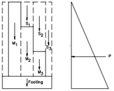
The total resisting force (F) will be a summation of the weight of each element, while the total resisting moment (MR) will be an aggregate of the product of each resisting force and its moment arm (a).
![]()
![]()
Check Safety Factors
Following design criteria, the overturning moment safety factor and the sliding safety factor should be above 2 and 1.5 respectively. Moreover, the overturning moment safety factor (MSF) is given as the ratio of the total resisting moment (MR) to the overturning moment (MO).
![]()
While the sliding safety factor (SSF) is a ratio of the product of the soil friction coefficient (μ) and total resisting force (F), to the resultant pressure (P) acting on the base of the wall.
![]()
