Etukudo
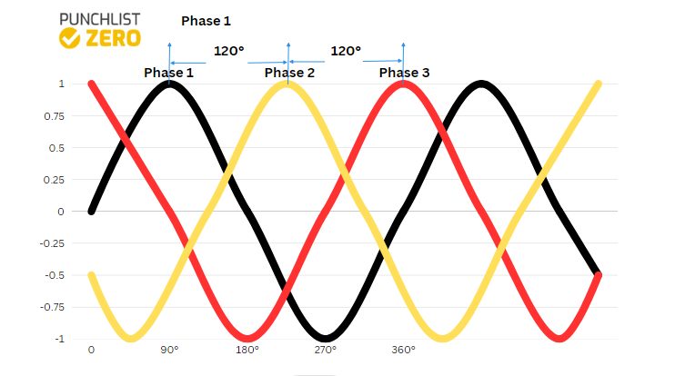
Three-phase voltage refers to power supply using three separate conductors carrying the same voltage, but in different phases. Moreover, any equipment that is connected to all three phases would experience peak electrical power from each phase at different times. As a result, steadier power output results than in single phase ac supply. In this article, you will learn more about three-phase voltage, review its formula, and the three-phase voltage stabilizer.
More on Three Phase Voltage
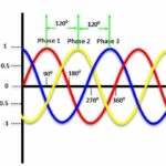
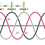
Generally, a three-phase voltage configuration consists of three conductors carrying the same power. However, each phase is at 120° to the other, meaning that each power line achieves peak voltage/current/power at different times. This configuration is an improvement of the single-phase systems as it offers the following advantages:
- Ideal for running industrial loads and does not need additional starters for large motors, unlike single phase voltage.
- The 120° phase difference between lines helps in delivering a smooth power output.
- Because the power is delivered by three separate lines, it allows for the use of smaller size conductors. Thus, it is a cost-effective solution for powering large loads.
Common three-phase configurations are the Delta and the Wye or Star configurations.
Delta Configuration
The delta configuration is the ideal setup for AC power transmission with its name stemming from its system of interconnection. All three coils are in series to form a close mesh as the figure below shows.
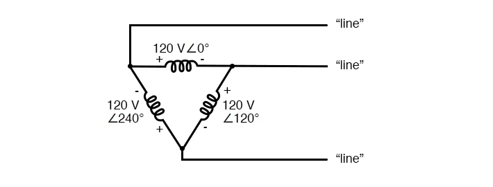
This interconnection appears to create a short circuit, but this is not the case because of the phase difference between each source. Rather, a balanced system produces an algebraic sum of all voltages around the mesh as zero. Most delta transmissions utilize three wires, but it is possible to introduce a neutral line by a center tap on one of the coils.
Wye Configuration
This is the more popular option in AC power distribution. Forming this configuration involves connecting similar ends (starting or finishing) of each coil together to form a neutral point. So, this configuration usually utilizes a neutral line.

At transformers, where power transmission transits into distribution, it is possible to maintain the same three-phase voltage configuration or change it depending on the following scenarios.
- A Wye-Wye configuration is used for small currents and high voltage.
- Delta-Delta is ideal for large currents and low voltages.
- Delta-Wye connection suits step-up transformers at power generation stations.
- Wye-Delta connection is for step-down transformers where transmission ends.
How to Calculate Three-Phase Voltage
When calculating three-phase voltage, there are two important concepts to consider, which are line and phase voltage. Line voltage is the amount of voltage between any two lines in a balanced system. Whereas, phase voltage refers to the voltage across any one line or component in a balanced system. Determining any of these parameters depends on the configuration in place.
Calculating Voltage in Delta Configuration
For delta configurations, the line voltage (Eline) and phase voltage (Ephase) are always the same. This is because the connection between each pair of line conductors is directly across a single winding in the circuit.
![\[ E_{line}=E_{phase} \]](https://punchlistzero.com/wp-content/ql-cache/quicklatex.com-daf81daccc773f6814376b13a4ad8152_l3.png "Rendered by QuickLaTeX.com")
As a result, the delta configuration can only deliver a single voltage value.
Calculating Voltage in Wye Configuration
For a Wye configuration, the line voltage always exceeds the phase voltage. If the system is balanced, the relationship between the line voltage (Eline) and the (Ephase) phase voltage will be as follows:
![\[ E_{line}=E_{phase}\sqrt{3} \]](https://punchlistzero.com/wp-content/ql-cache/quicklatex.com-a455f695dc961638d32e5b30ade97cbd_l3.png "Rendered by QuickLaTeX.com")
As a result, the Wye configuration can deliver different voltages to a load in a system. Thus, it is more flexible than the Delta configuration.
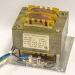
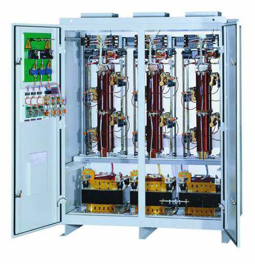
Three Phase Voltage Stabilizer
Because of the sensitivity and cost of certain industrial and commercial equipment, it is necessary to finetune incoming power. Three-phase voltage stabilizers serve as a gateway between the power source and the load to achieve this finetuning. These stabilizers continuously monitor the incoming mains supply and automatically control the output voltage to meet prerequisite levels.
As a result, the load enjoys protection from harmful surges, spikes, and transients. More sophisticated applications use voltage stabilizers equipped with power line conditioning features to provide enhanced protection and noise filtration. Historically, servo electronic-based stabilizers have dominated the market. But in recent times, static electronic stabilizers have become popular due to the speed of microprocessor control.
There are several factors such as load type, output power, and power factor, which influence the selection of a voltage stabilizer. Moreover, key tips for selecting the capacity of voltage stabilizers, otherwise known as automatic voltage regulators, are as follows:
- The three-phase voltage stabilizer should be between 1.5 to 2 times the power if protecting purely resistive loads. Examples of these are electric heaters, resistance wires, and incandescent lights.
- If the loads are capacitive such as water pumps, air conditioners, and computers, then the three-phase stabilizer should be three times the load. Moreover, when the capacitive load is very large, there is greater demand on the starting current. In some occasions, this could be between 5 to 8 times more. The voltage stabilizer has to deliver over three times more power than the load.