Structural skids allow for the mounting of equipment to a piping system, and for fabrication to occur in a shop environment. This reduces cost and complexity compared to equipment integration in this field. In this article, you will learn about skid engineering, design, construction, testing, and accessories.
Structural skids provide cost-effectiveness and quick turn fabrication. Their design may contain either a complete process system or to serve a specific function. Structural skids may also systematize a manufacturing process into logical units.
While skid designs vary according to client specifications, all skids provide the following elements:
- Portable design – Skid systems provide self containment and easier transport over field fabrication units.
- Accessibility – Skids have an accessible layout that is compliant to codes and regulations while allowing access to critical process equipment.
- Small footprint – The organization of tanks, piping, and necessary process equipment allows for the smallest footprint possible.
- Controlled assembly – Skid usually occurs in a controlled facility where access to welding materials, pneumatic air, and overhead lifts is available.
- Process Connections – Process connections can gather into one spot on the skid or be placed at “tie-points” that have been specified by the client.
- Factory Acceptance Testing (FAT) – A completed FAT prior to shipment ensures the system operates as designed and reduces on-site startup time.
Skid Engineering
Engineering a skid requires the determination of main member size, cross member size, intermediate angle iron, and floor plate thickness. In beam sizing and construction, engineers should consider static, dynamic, and quasi-static forces require consideration. Skid rigidity provides a major factor in sizing a beam size and measures by allowance deflection in inches. This number is calculated by taking the length of the skid in inches and dividing by a set integer. Typical skids receive rigidity requirements of L/240 whereas demanding applications may see rigidity requirements of up to L/960.
Static Forces
Static skid design evaluates stress and buckling of members under constant load forces. The following static loads require analysis:
- Dead loads, including permanent equipment weight.
- Thermal loads, including forces generated by temperature/pressure change.
- Drive torque of compressors/engines.
- Lifting or dragging loads. These loads include a load factor from impact of sudden stops/motion of lifting equipment (load factor of 1.15-2.0 is common.)
- List angle, which creates horizontal loads.
Dynamic Forces
Dynamic loads originate from waves, earthquakes, wind or machinery and evaluated by the resulting vibrations and fatigue. Resonance is a condition where the frequency of dynamic force is +/- 10% of the mechanical natural frequency of the skid foundation. This may occur as a result of dynamic loads. Common dynamic forces include:
- Unbalanced forces generated by rotating/reciprocating weights such as piston assemblies. This is a frequent concern in reciprocating compressors.
- Horizontal cylinder gas forces.
- Vertical forces, created when rotating motion converts to reciprocating motion.
- Pulsation-induced shaking forces, created at elbows/changes in pipe diameter.
- Misalignment of compressor and driver.
- Rolling torque on engines (occurs at higher orders of engine run-speed).
- Torsional vibrations, which may cause horizontal vibrations of the frame.
Quasi-static Forces
Quasi-static forces are periodic loads that have a frequency of less than 3 Hz. Their skid design evaluates stress, buckling of members and fatigue. Typical quasi-static loads include:
- Environmental loads like wind, current, wave, live loads, ice, seismic and hydrostatic pressure that occur in any direction.
- Construction loads, including installation, loadout and transportation.

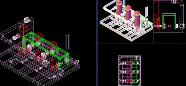
Skid Design
An engineer uses a Piping & Instrument Diagram (P&ID), specifications, 3D model, general arrangement (G/A), and skid calculations as the basis for the structural skid design. The finished product is a highly detailed 2D drawing of how the skid is constructed. The welding method, material type, and lifting requirements require consideration in the skid design.
Welding Method
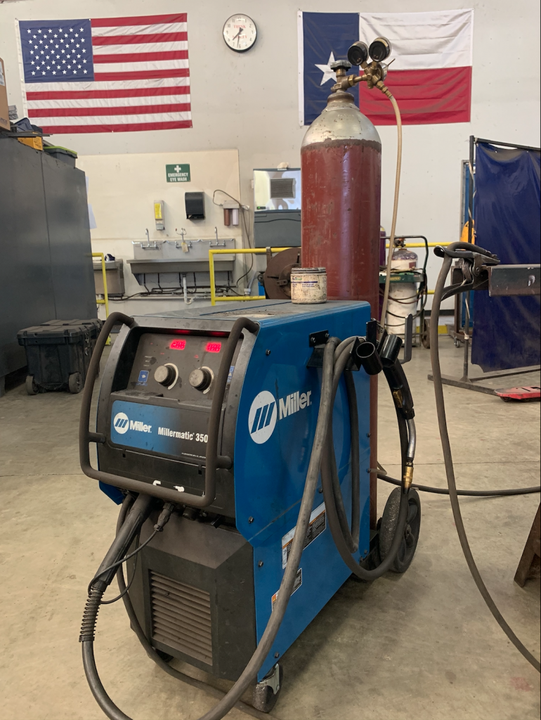
The following methods are commonly utilized in the development of skids.
- Gas metal arc welding (GMAW) – This process forms an electric arc between a consumable MIG wire electrode and the workpiece metal. Heated metal melts and joins together.
- Flux-cored arc welding (FCAW) – This semi-automatic/automatic arc welding process requires continuously fed voltage to join metals.
- Metalcore arc welding (MCAW) – uses heat generated by DC electric arc to join metal in the joint.
Additionally, weld characteristics are specified on the skid drawing itself, or more generically on a weld map. The type of welds varies greatly. Most welding done on skids are filet welds in a skip or seam configuration. The skip weld alternates between non-weld and welded segments whereas the seam weld applies continuously along the joint.
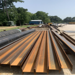
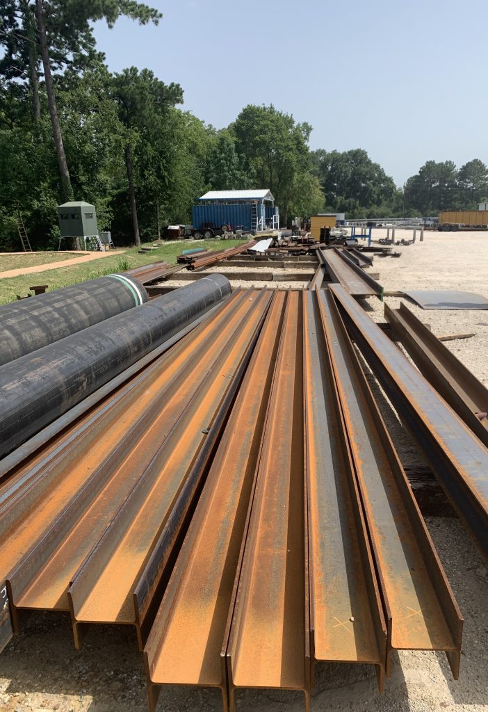
Material Type
Structural skids may require specific materials for construction due to reasons such as heating elements, structural strength, and durability. Carbon steel is the most common skid material. Stainless steel appears in the industry at times, with alloys, fiberglass, and plastic being much rarer. Most projects utilize steel materials due to their structural integrity, non-malleable properties, and low cost.
Lifting Requirements
Completed structural skids require lifting studies to be conducted. This ensures the skids can be lifted, transported to site, and withstand environmental loads (e.g induced wind or earthquake).
Transportation methods of completed structural skids from shop to client site is critical to consider and may vary depending on the type of skid. Lifting eyes allow for vertical lifting from a single point or multiple points and see primary use on heavy skids. The working load limit depends on the angle of pulling force and can range from 160-24,000lbs. Forklift pockets apply to smaller and simpler skids and may install near the bottom of the skid structure for easy conveyance between the customer and engineer.
Engineers should apply appropriate consideration to the skid structure for the environmental factors of the site location (e.g seismic factors, wind loads, heat factors.) Calculating the center of mass of the skid will aid depicting ensure a safe and secure removal process. Pull tests (a push/pull force on a structure) may be necessary to ensure parts of the skid are fixed and secure, without jeopardizing the structural soundness of the skid.
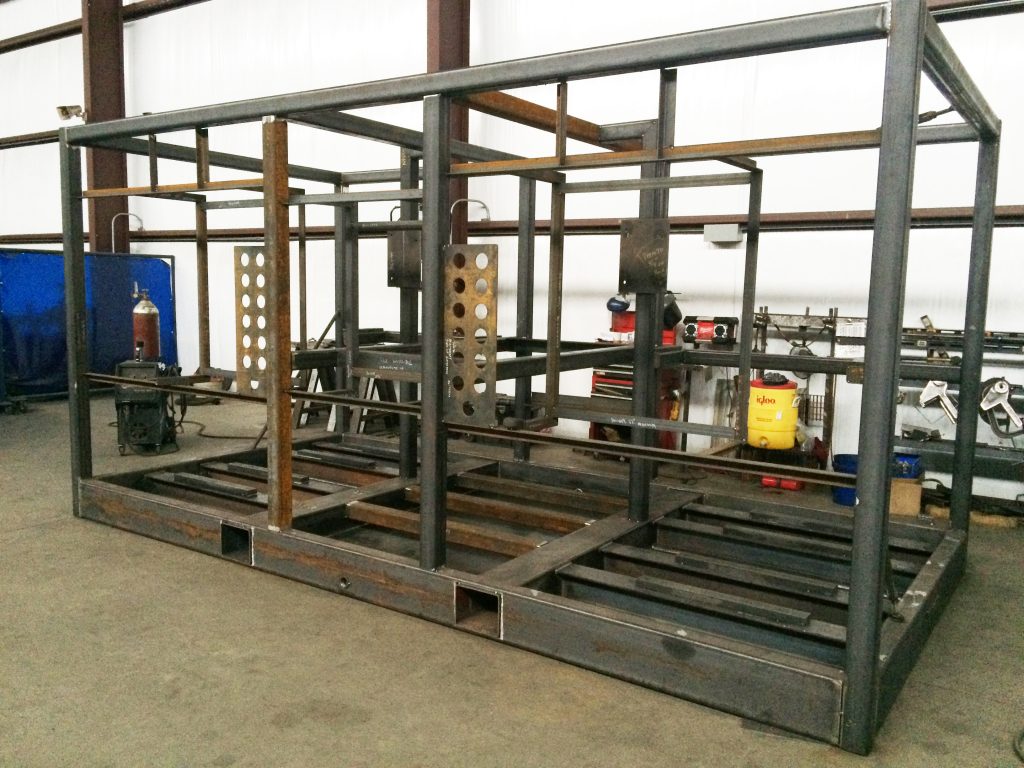
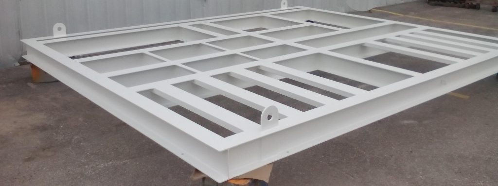
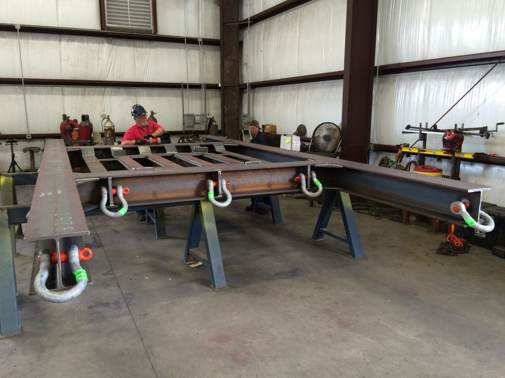
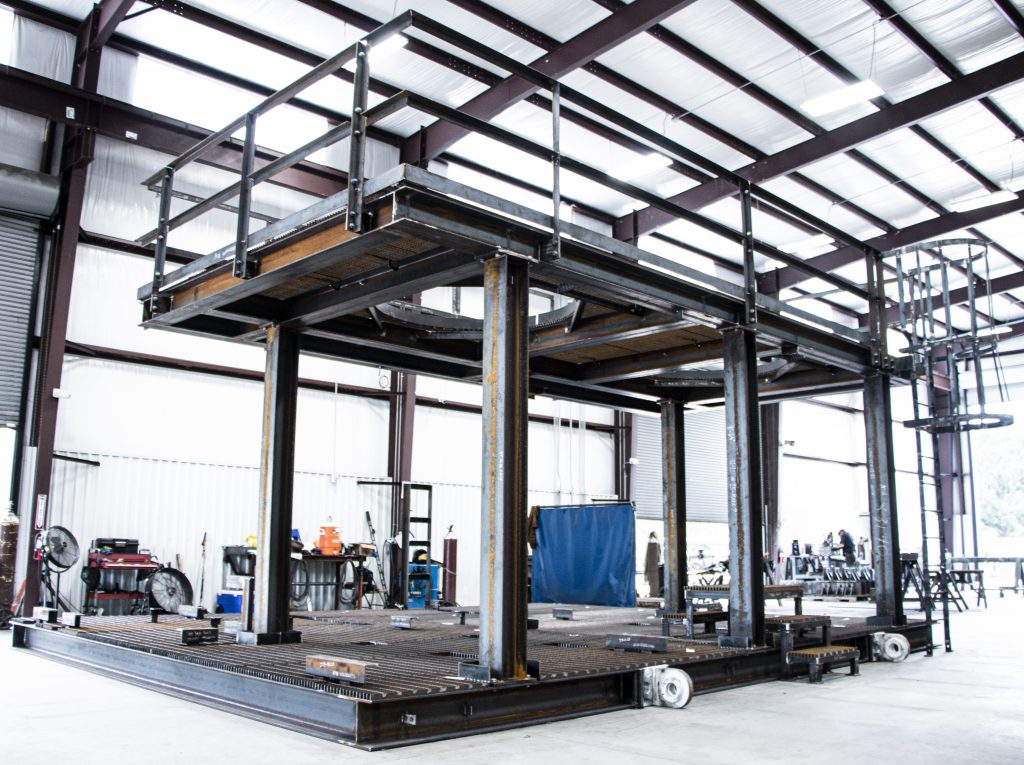
Construction
Skids construction requires the assembly of main beams, cross members and angle iron, floor plate, lifting lugs, drains, and a protective coating.
Main Beams
Main beams are also referred to as perimeter beams. Construction of these beams is critical for correct sizing and build of the skid. The joining of these beams sets the perimeter for the later addition of cross members.
Cross Members and Angle Iron
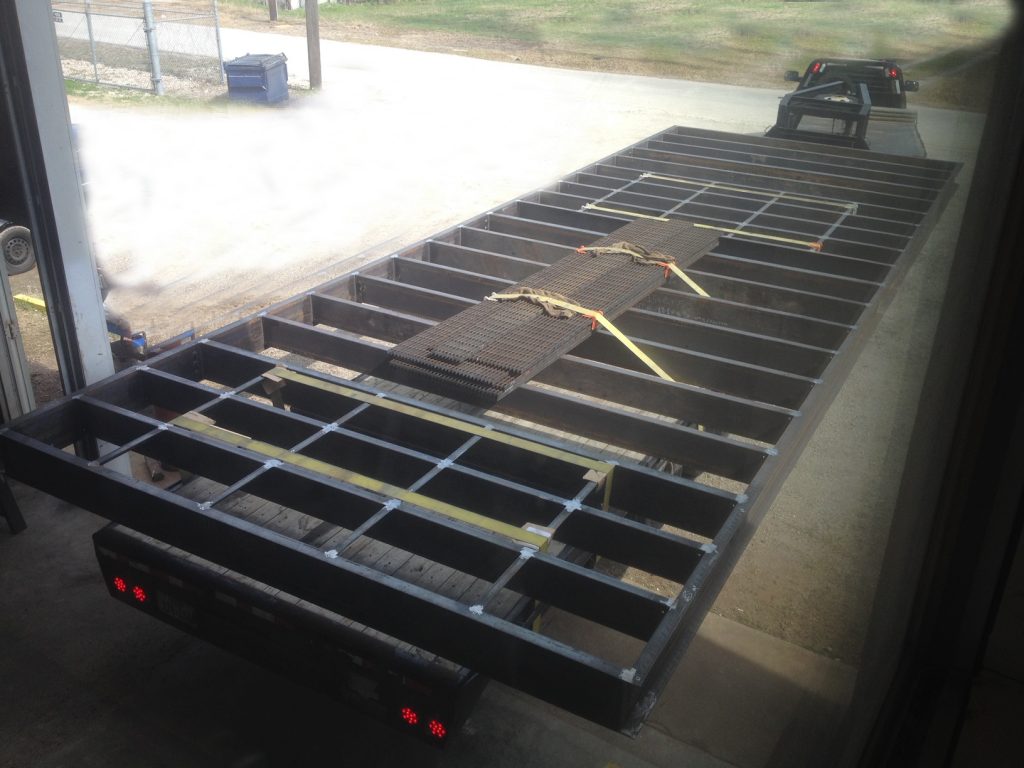
Cross members and angle iron connect to perimeter beams in a method dictated by the structural calculations. Cross members add strength to the structure, where angle iron is typically to reduce floor plate deflection.
Floor Plate
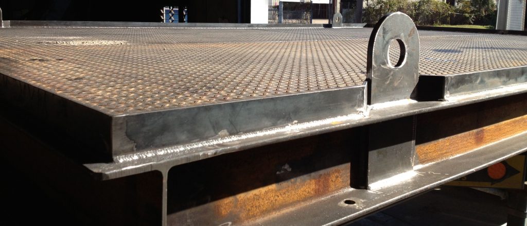
A floor plate, sometimes referred to as a skid plate, secures to skid beams to allow for safe foot traffic. Floor plates generally originate from the same material as the accompanying beams. Checkered floor plates are ideal for skids that face corrosion threats and heavy traffic. Floor plate requirements depend on customer choice of grade, thickness, width, and length.
Lifting Lugs
If the skid is designed for overhead lift, lifting lugs are supplied either in a removable or bolt-on format. Lifting lugs may be cut from a plasma machine at the shop facility or procured externally.
Drains
Skids that involve piping require drainage system requirements. The angle between the discharge pipe and attributed pipe must be at least 90 degrees, with the minimum installation depth of the pipeline ranges from .5-.7m.
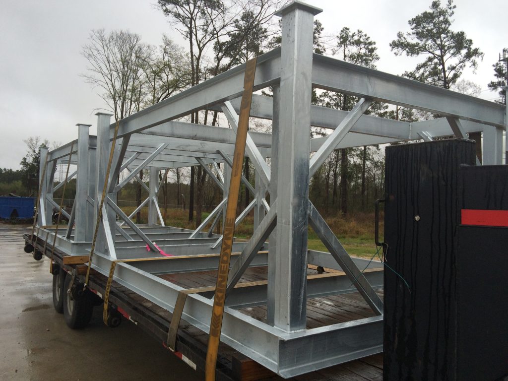
Protective Coating
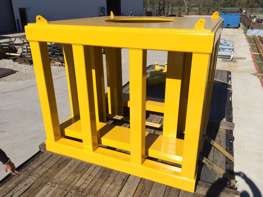
Paint specifications may be specified in order to prevent corrosion of carbon steel and in rare cases, stainless steel. A multi-coat system is standard and provides an all-weather sealant that protects against corrosion, scratches, impact, abrasion, chemical exposure, and UV rays. Galvanization, the process of dipping a skid into molten zinc, provides a metallurgical bond and a highly protective coat.
Testing
Engineering specifications, detailed design, and quality process reviews ensure compliance to the specified requirements. Specifications may require non-destructive testing for weld verification to ensure welding meets requirements. Skids that are part of a process system undergo a factory acceptance test (FAT). The FAT occurs at the final stage of the project and proves that the equipment integrity and functionality is suitable, and to design and user requirements.
Accessories
Depending on functional and access requirements, structural accessories may be required. Common accessories include:
- Handrails
- Stairs
- Platforms
- Structural equipment stands
Completed structural skids must also comply with OSHA requirements and local building code.
This article is brought to you in collaboration with Grimes Industrial, Inc of Tomball, TX. Grimes Industrial provides structural skids along with a litany of other steel fabrication services. Contact them at info@grimes-industrial.com or 713-921-0000 for any steel related fabrication needs.