Running torque refers to the amount of torque a device needs to maintain the constant angular velocity of a rotating part once in operation. Knowing this value provides important operating information for rotation machinery and requires testing to determine it. In this article, you will learn about running torque vs other types such as holding, prevailing, and breakaway torque, and applications in industry.
Running Torque vs Holding Torque
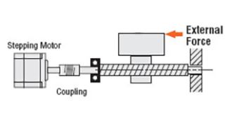
A stepper motor, commonly used in motion control applications, divides a full rotation into an equal number of steps. For such a motor, the holding torque equals the amount of torque to move one full step when the windings are energized but the rotor is stationary.
In addition, for such a device to be precise in its application, engineers need to carefully size the motor with respect to torque and speed. The holding torque (Τ) is a product of the motor’s torque constant (Kt), and the current (I) in the stator windings.
![]()
From this formula, the maximum current the motor can withstand is the limiting factor of the holding torque. On the other hand, running torque is associated with servo motors for the positioning of loads during longer strokes. Typically, for an equivalent motor, the holding torque is higher than the running torque. Because running torque (Tr) is what sustains a device at its normal operating rotational speeds, it is a function of the motor power requirement (P) in horsepower, and the motor speed (N) in rpm.
![]()
Running Torque vs Prevailing Torque
Prevailing torque refers to the torque that a technician requires to overcome friction to screw a locking nut down a thread. In addition, this torque is not to produce clamp load or bolt stretch. Often, applications require that the prevailing torque is sufficient to overcome intentional interferences in the bolt joint design such as Nylok patches, squeeze nuts, etc. Also, it is to overcome unintentional interferences which include weld spatter, contamination, and cross-threading.
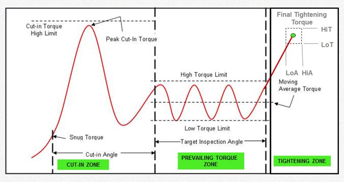
Because of these varying conditions, the application of prevailing torque is a lot more complex in comparison with running torque. Thus, engineers use various strategies in applying prevailing torque to fastening devices. In particular, one of such strategies is the Prevailing Torque Strategy (PTS) popularized by the equipment manufacturer Ingersoll Rand. The PTS involves the altering of the torque value of the fastening device across segments of the process as follows:
- Cut-in Zone: The torque of the fastening device attains a peak value (Cut-in Torque) to overcome static friction and initiate the fastening process. Monitoring the torque value in this zone reveals poor quality conditions of a bolted joint such as tightening obstructions and undersized holes.
- Prevailing Zone: This zone checks the mean and peak prevailing torque as fastening continues to ensure that it falls within set limits. In addition, this zone determines the seating point where the final tightening begins.
- Tightening Zone: The final tightening is done in line with a set approach: angle controlled, torque controlled, or yield controlled.
Running Torque vs Breakaway Torque
Breakaway torque refers to what a motor needs to start moving a stationary load. Generally, its value is higher than the running torque, which keeps the load rotating at operational speed.
However, the need for a breakaway torque in a device is only for a short period, usually during startup. According to the nature of the machinery and the type of bearings in use, the breakaway torque typically varies between 120% and 600% as the table below highlights.
| Type of Machinery | Breakaway Torque (as a % of Running Torque) |
| Typical machinery with ball or roller bearings | 120-130% |
| Typical machinery with sleeve bearings | 130-160% |
| Conveyors and machines with significant sliding actions | 160-250% |
| Machines with high load points such as cams and cranks | 250-600% |
Determination of Torque
In practice, engineers carry out testing to determine the various torque values of a device. This holds particular importance specially in fastening applications and in rotating machinery. During testing, a torque transducer is placed between the tool applying the force, and the item on which the force acts. Subsequently, measurements are gotten using either of the two approaches:
- Reaction Testing: In this approach, the transducer measures the amount of torque that can prevent the item on which the force acts from rotating.
- In-line Testing: On the other hand, in-line testing measures the torque the device needs to turn the rotating part.
Applications in Industry
In engineering, running torque is an important measure for machinery and other applications involving rotating parts.
Torque to Turn Testing
This testing involves measuring the turning moment that a device requires to make one component rotate about another. In this testing, the running torque gives an indication of the resistance in a system. Monitoring the running torque during this testing reveals other details such as smoothness of running, lack of concentricity, and defects resulting in observable chattering.
Servo and Induction Motors
Servo and induction motors operate at set speed limits. As a result, running torque is an important specification for these devices. For an induction motor, the running torque (Tr) is a function of slip (s), rotor reactance (sX), per phase resistance (R), and a constant (K).
![]()
