Etukudo
The helical spring constant, more commonly referred to as the k value, provides key information about a spring’s stiffness capacity. A greater k value is indicative of a greater restoration force or rigidity of a helical spring system. In this article, you’ll learn the helical spring constant formula, determining the k factor, parameters that affect the spring constant, and applications in industry.
Helical Spring Constant Formula
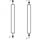
The helical spring constant (k) is a proportionality constant. It depicts the relationship between a force (F) required to extend or compress the spring, and the length (L) of extension or compression achieved by this force. The helical spring constant formula is also known as Hooke’s law.
F ∝ L
F = kL
Determination of the Helical Spring Constant
Determining the k value of a helical spring is of utmost importance. Moreover, the helical spring constant value guides the suitability of a spring for an application. As a result, systems that require more rigidity utilize springs with high k values. Springs with low k values suit more flexible systems. Finding out the constant of a helical spring experimentally demands the use of basic apparatus and a straightforward procedure.
Apparatus Procedure
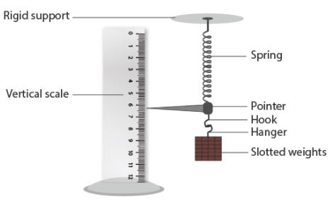
To determine a helical spring constant requires the following:
- A rigid support: This holds one end of the spring in a fixed position.
- Helical spring: The spring whose constant requires determination.
- Multiple weights: Five or six units of a standard weight for loading the spring.
- Hook and hanger: These attach the spring to the weight.
- Vertical scale: Measures spring extension as the weight displaces it.
- A fine pointer: Aids in producing precise measurements of spring extension.
Procedure
With the apparatus set, the procedure for determining the helical spring constant is as follows:
- Suspend the spring from the rigid support and attach the pointer and hook to its lower end.
- Place the weight hanger on the hook.
- Place the vertical scale such that the tip of the pointer is just over the markings/divisions on the scale. Avoid contact between the scale and pointer throughout this experiment.
- Now, record the scale reading.
- Carefully place a unit of the standard weight (e.g. 30g or 50g) on the hanger.
- Wait till the tip of the pointer comes to rest then record the new reading on the scale.
- Repeat steps 5 and 6 for each unit of the standard weight until all the units are on the hanger.
- Gently remove a unit of the weight and record the scale reading.
- Repeat step 8 until only the hanger remains.
- Plot a graph of the force (x-axis) and extension (y-axis).
- Find the helical spring constant using its formula as follows:
k = F/L
Parameters that Affect the Helical Spring Constant
There are several parameters that affect the helical spring constant. It is important to understand these parameters so that you can alter them to attain the desired k value.
Wire Diameter
The diameter of the wire used in making a helical spring will determine the spring’s constant. A larger diameter wire makes the spring stiffer, thus a larger k value.
Coil Diameter
The manufacturing process of a helical spring involves the wrapping of a steel wire around a cylinder. Implying that it is the diameter of this cylinder that governs the coil diameter of the spring, and ultimately influences the spring constant. A larger coil diameter gives a more flexible spring than a smaller coil diameter.
Number of Active Coils
When you place a load on a spring, the number of active coils refers to the number of coils that extend or compress. Having more coils results in a lower spring constant.
Free Length of the Spring
This is the length of a helical spring without any load on it. The ratio of the mean diameter of a spring to its free length determines its slenderness ratio. A slenderness ratio exceeding 3 means that the spring easily buckles/bends under an applied force. It is uncommon to have springs with a slenderness ratio exceeding 3.
Material of the Spring
The type of material used in manufacturing a spring will affect its stiffness. This is because different materials have a unique shear modulus of elasticity. Shear modulus of elasticity refers to the inherent ability of a material to resist deformation when a force exerts on it.
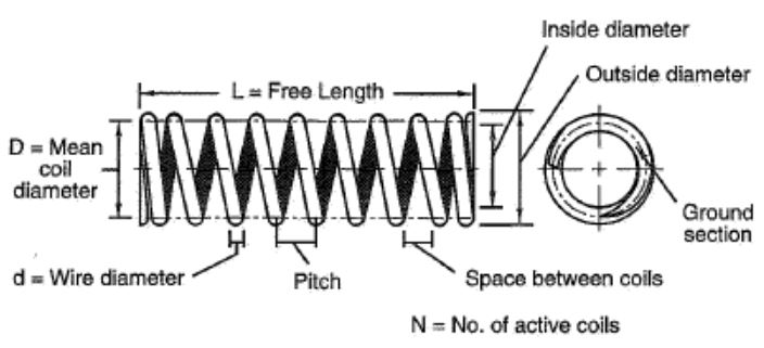
The way these parameters affect a helical spring constant is clearer to see in a formula. In the following equation, the wire diameter (d), mean coil diameter (D), number of active coils (N), and the shear modulus of elasticity (G) clearly have an impact on a helical spring constant (k).
k = (d4 x G)/(8D3 x N)
Applications of the Helical Spring
The purpose of helical springs is to store and release energy when there is impact or shock. Furthermore, they serve to resist compressive or pulling forces between objects. As a result, a wide variety of systems utilize them. Reviewing the three main types of helical spring designs helps to understand their applications better.
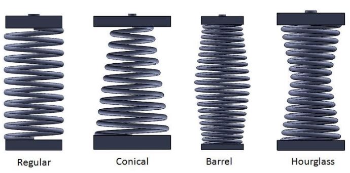
Compression Helical Springs
These are by far the most common helical springs on the market. They have an open-coil design, which is set at a pitch to resist compressive forces that tend to bring objects together. Compression helical springs come in a variety of shapes and sizes such as conical, hourglass, barrel, and regular shape. However, all shapes are designed to buffer the compressive forces of a particular load. For this reason, applications such as ballpoint pens, furniture, vehicle suspensions, and actuators, that require load buffering often use compression springs.
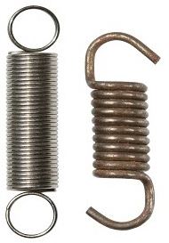
Tension Helical Springs
Tension helical springs are also known as extension springs. Unlike compression springs, their coils have a tight winding with hooks or loops at either end. Because of this design, they resist any pulling force that tends to move components of a system apart. Consequently, it is the load requirements of a tension spring that determines its tightness. Also, this tightness of its coils is what gives it sufficient energy to restore diverging components of a device to a neutral position. Tension helical springs are used to extend or retract aircraft landing gears, to hold equipment to oil rigs in offshore applications, and in self-shutting doors.
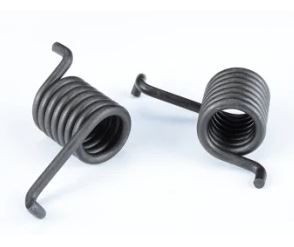
Torsion Helical Springs
Torsion springs are spiral-shaped helical springs that store energy when you rotate it about its axis. When you load this spring, it responds with a torque force proportional to the amount of force loading it but in the opposite direction. In addition, torsion springs are ideal wherever there is a need for rotational force. Such applications include door hinges, mechanical watches, levers, and switches.