Etukudo
Proper wiring of a shunt trip breaker is necessary for it to perform its role of protecting all downstream devices in its circuit. Although it performs the same function as other circuit breakers, it also has its peculiarities. In this article, you will have an overview of a shunt trip breaker, learn its wiring process, review its diagram, and requirements for use with an elevator.
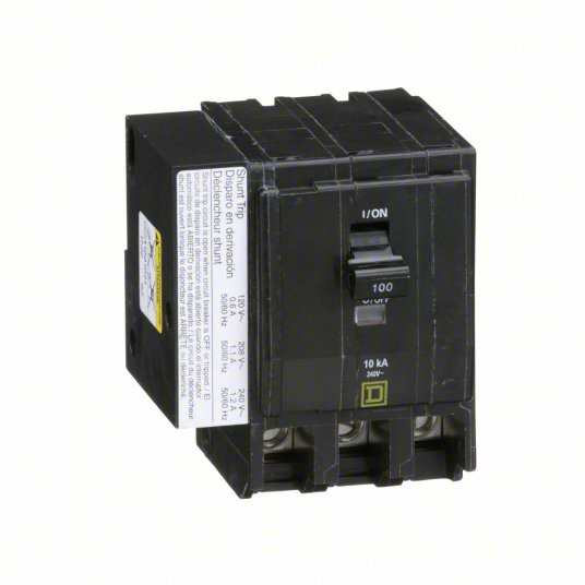
Overview of a Shunt Trip Breaker
A shunt trip breaker is a type of breaker containing an electric coil and a plunger. After energizing the coil manually or automatically, the plunger operates to trip the main breaker. Generally, it does not work on its own, rather it serves as an accessory to the main circuit breaker. In the main breaker, such as a GFCI, there is one tail wire for neutral connections only. If there is any short, then it trips the circuit. However, in a shunt trip breaker, there is a second wire available for connection to a control source that enables tripping of the circuit remotely or automatically. As a result, the shunt trip breaker has an extra dimension of being able to trip the circuit for other reasons other than a short.
For example, a building can have a smoke detection system and a shunt trip installed together. So that if the sensor detects smoke, it can trip the breaker via the communication line of the shunt trip. It can also serve as a manual emergency switch to the main breaker by installing it as a remote switch. The extra layer of protection and sophistication that comes with having a shunt trip breaker also incurs more cost. Which means it is usually avoided, and in fact, not necessary for residential applications but is compulsory for industrial applications. For instance, commercial kitchens use it in compliance with ANSI/ASME CSD-1, while escalators and elevators use it in line with ASME A17.1.
Wiring Process
For a shunt trip breaker to function effectively, the wiring should be according to the manufacturer’s specifications. Knowing that it always operates alongside a regular circuit breaker, compatibility is key when selecting both breakers. This section reviews the necessary steps to take during installation of a shunt trip.
Assess Breaker Compatibility
Shunt trip is an accessory, and not all breakers are compatible to it. Some breakers have built-in provision for connecting it, while others can only pair with specific models. Moreover, there are breakers that require factory installation of the shunt trip accessory, so it is necessary to evaluate all these options.
Install Shunt Trip Accessory
Although manufacturers have different installation procedure, they generally follow this pattern:
- Open the circuit breaker to expose the terminals. Usually, a flathead screwdriver is enough to perform this task.
- Put the wires in the hole near the shunt trip and insert the insulator into its correct position.
- Secure the shunt trip to its location before covering the circuit breaker.
Connect Shunt Trip to Panel Board
Before proceeding to this step, ensure that there is no power in the system by switching it off in the mains and confirming with a tester. Then, open the panel board and connect the shunt trip breaker to the main power supply. Also connect the mainline and the supply wire to the circuit breaker.
Review Wiring Diagram and Connect Safety Control
Review the wiring diagram of the shunt trip circuit breaker before making the safety control connections. With proper understanding of the diagram, connect one wire of the shunt trip to the neutral connection. While the other wire of the shunt trip goes to a kill switch. Connect the supply to the other terminal of the kill switch to complete the process. When locating this kill switch, consider accessibility in times of emergency. For example, a good place to put it is near an emergency exit.
Test the Unit
With all the connections in place, restore power through the mains and test the shunt trip using the kill switch. If power does not go off after pressing this switch, then review the connection.
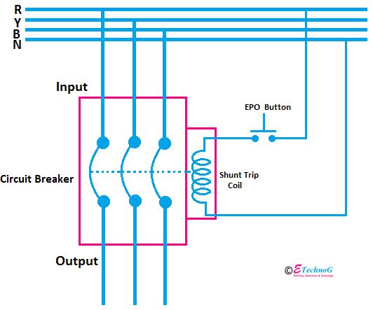
Shunt Trip Breaker Diagram
Reviewing a shunt trip breaker diagram is a critical step in ensuring the correct installation of the device in a circuit. Generally, it is a simple diagram like the one below, and requires strict adherence for the device to work appropriately. From the diagram, the EPO (Emergency Power Off) button or kill switch is in series with the shunt trip coil of the main circuit breaker. The EPO is a normally open switch, which is closed to transmit power to the shunt trip coil that trips the breaker. This is how the connection is for the manual shunt trip. For the automatic version, the diagram remains the same, just that the EPO is replaced by a control system.
Shunt Trip Requirements on an Elevator
Using a shunt trip breaker on an elevator is not a straightforward process. First, in the case of an emergency such as a fire outbreak, elevators usually have a recall function that sends the cab to safe floors. Concurrently, the fire alarm triggers the sprinkler system in the building, which could lead to any of the following:
- Invasion of water into the elevator braking system.
- Elevator reacting erratically due to shorting of controls.
- Risk of shock or electrocution.
To prevent any of these from occurring, there are certain requirements from industry regulators. For example, the NFPA 72 requires all heat detectors that serve to shut down elevator power, to be within 24 inches of each sprinkler head. In addition, these heat detectors are to have both a lower temperature rating, and a higher sensitivity relative to the sprinkler. Another code, the ASME A17.1, specifies that there shall be an independent means of automatically disconnecting the main power supply from the elevator controls. These industry regulations highlight the need for a shunt trip breaker. Some requirements when using a shunt trip for an elevator include:
- Shall operate independently and not be self-resetting.
- Shall switch off power in the elevator before water enters controls.
- Can be programmed to delay briefly, to allow the cab move to a suitable level for occupants to exit.
- Shunt trip control circuits shall be constantly monitored for operating voltage. If this is not present, then a supervisory signal shall be indicated at the fire alarm control unit.