The terms safety valves and relief valves are often used interchangeably for pressure relief devices. Both valve types allow for overpressurization relief in a process system, but operate differently. In this article, you will learn about the working principle of safety and relief valves, types, sizing and standards, applications, and maintenance and repair considerations.
Working Principle
Relief and safety valves avoid system failures by changing operating behavior in an overpressurization scenario. This change in operating behavior protects equipment and personnel by regulating pressure. Relief valves push overpressurization gas or liquid back to the low-pressure side, where safety valves vent the overpressurized air/gas out of the system.
Relief Valve Operation
A relief valve opens when the vessel or pipe pressure increases to a specified pressure point. The set-point of a relief valve is usually set at 10% above the working pressure limit. The opening of pressure relief valves is proportional to line overpressurization. Once pressure returns to normal, the pressure relief valve closes.
Safety Valve Operation
Safety valves release excess pressure as they open immediately and fully to prevent the overpressure condition. The set-point is set at 3% above the working pressure limit, and they are divided into a wide range of sub-types based on their use and design for different processes.
Types
Safety and relief valves may open via spring loading, diaphragm, piston, pilot, or the dead weight method.

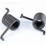
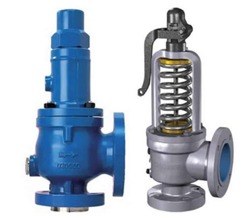
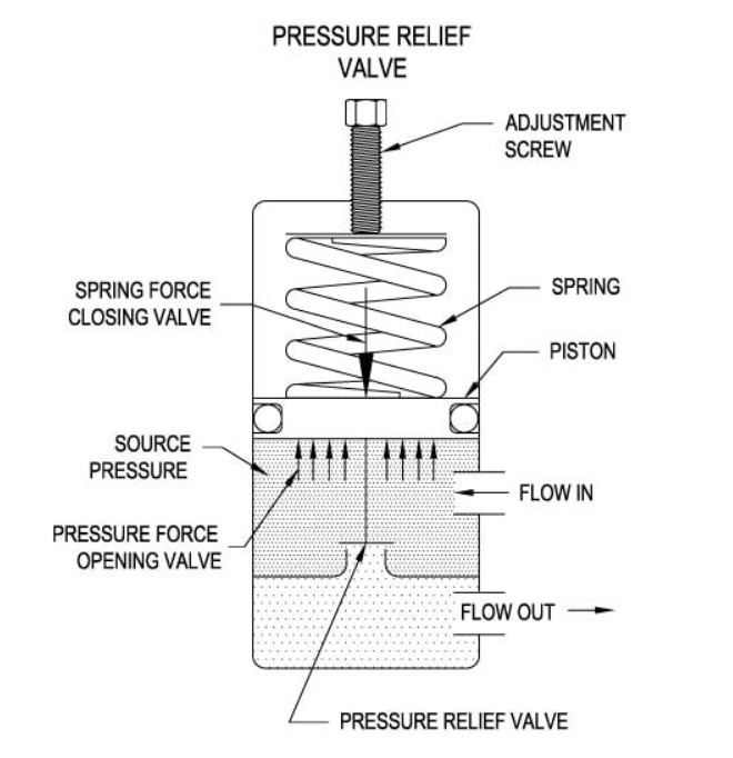
Spring Loaded
A spring attached to a lever attached in the middle, which is pulled downwards. The lower end of the spring is attached to the valve’s body and is held tight its place by the spring force.
The valve rises against the spring force when pressure exceeds the normal working pressure and allows the excess steam to escape before returning to its normal state. It’s light and compact design is preferred in stationary boilers and locomotive and marine services.
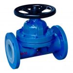
Diaphragm Type
The diaphragm type valve is suitable for low-pressure applications and safe to use in liquid systems. Diaphragm relief valves operate in similar fashion to diaphragm valves. A thin disc-shaped element senses overpressurization and then fluid discharges via a pilot valve.
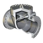
Piston Type
There are multiple types, and variations in the piston valve, consisting of a disc, guided in its movement by a vented guide. The active area of the top and bottom surface of the disc is equal to balance the additional forces.
Any additional back pressure does not affect this valve as it consists of the main valve, which includes the obturator or the piston shaped closing device. The piston-type sees more friction than the diaphragm option.
Pilot Operated
The pilot operated safety valve uses the fluid to apply the closing force on the safety valve disc. These valves offer good over pressure and blow-down performance, so they are used with narrow margins of the set-pressure and system operating pressures. They are available in many sizes and can be attained as per requirement.
Dead-Weight Pressure-relief Valves
The dead-weight safety valve is usually made of gunmetal, also known as ‘Red Brass’ due to its resistance to corrosion from steam and saltwater. The valve rests on the gunmetal seat, fixed to the top of the vertical steam pipe, and has a flange at the bottom to attach at the top of the boiler shell. When the steam pressure exceeds normal working pressure, the valve is lifted with its weight to let the excess steam out. It is one of the simplest relief valves from the design perspective.
Sizing and Standards
The most important consideration regarding safety and relief valves is safety. Safety for the plant, equipment, and the piping system must be ensured. While selecting a safety and relief valve, the following considerations are to be kept in mind:
- The size of the valve must correspond to the size of the discharge and inlet piping.
- The set pressure must not exceed maximum allowable working pressure, and the valve must open when there is still a 10% margin.
- The operating and relieving temperatures are to be kept in mind.
- Valves should be selected such that the back pressure does not exceed 10% of the valve set pressure.
- The valves must be able to relieve the pressure at set capacity. This capacity can be determined by the applicable codes expressed in pounds per hour, standard cubic feet per minute or gallons per minute.
Engineering process dictates a systematic approach to relief and safety valve design. Valves can be designed on the basis of blocked discharge, gas blowby, fire, or any other parameter as dictated by the customer or project specifications. Block discharged sizing assumes that the valve must handle the total design flow rate and considers the condition in which all other inlets and outlets are blocked. Gas blowby determines the maximum flow rate by considering the case of upstream failure of a control valve or pressure regulator. Fire sizing a relief valve considers a case where the process is exposed to fire and thus pressure is increased to 120% of the maximum allowable working pressure.
Safety and relief valve sizing is subject to API and ASME/PED standards. API 526 provides basic design requirements for spring-loaded and pilot-operated valves and API 520 details sizing procedures and methods. Depending on the geographic region of installation, ASME or PED code deal with the testing, reparation, and certification process.
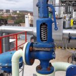
Applications
Safety and relief valves are widely used in many industrial applications that deploy boilers, vessels, and high-pressure piping. In nearly all of these applications, some type of overpressure relief mechanism must occur to protect operators and equipment. Most industrial plants and processes are subject to a hazard and operability study (HAZ-OP) where overpressurization conditions are evaluated.
Maintenance and Repair Considerations
These valves are usually maintenance-free devices. However, it is essential to check them for blockages several times a year in accordance with manufacturers’ recommendations as well as being regularly checked for broken/missing seal valves and leakage.
Due to the criticality of the pressure relief/safety device, repairs must be taken with great caution. The subject valve may be disassembled, and flaws corrected under the ASME VR stamp process. Repairs to a safety valve are typically due to improper installation or workmanship during commissioning.