Etukudo
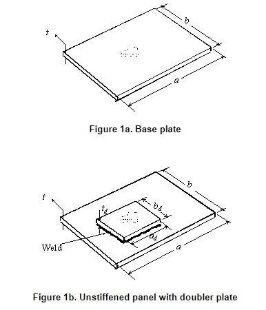
A doubler plate refers to a small piece of plate that is attached to a larger area, to provide strengthening in that location. In engineering, it is common to refer to it simply as “doubler.” In this article, you will learn about the application of doubler plates, and various considerations in their design.
Application of Doubler Plates
Doubler plates have two primary functions in fabrication. First, they offer a temporary solution to damage in a variety of structures such as ships and tanks. Moreover, they serve as a stopgap measure to repair defective welds, holes or cracks in plates, and plating affected by corrosion. The level of adoption of doublers is high, mainly because it is inexpensive and easy to deploy. However, professionals do not recommend their use on a permanent basis, so it is necessary to exercise caution in their application.
When using a doubler plate for repairs, there are factors that can affect their effectiveness, which include:
- The end conditions of the base plate.
- The type of material that the base plate and doubler plate are made of.
- The location of the doubler with respect to the base structure.
- The level of cracking or corrosion of the base material.
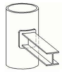
Another use of doubler plates is to increase web thickness and resistance against shear at structural connections. For example, a beam-column joint. When such a joint is subject to lateral loads, the panel zone, which is the region on the column around the joint, experiences significant shear stress. As a result, this region requires reinforcement by increasing its stiffness. This is where web doublers come into play. Unlike its use for structural repairs, the application of web doublers is on a permanent basis.
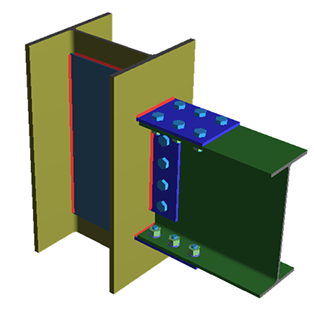
The use of web doublers increases the column web thickness as well as the panel zone shear capacity. Thus, it improves the fatigue and buckling strength of the joint. However, unlike their plate counterparts, web doublers are expensive to fabricate. Consequently, engineers should ensure that their use is necessary, and assess whether making the entire column thicker provides a cheaper option.
Doubler Plate Design
When designing a doubler plate, the recommendations from design codes and various studies focus on buckling strength, fatigue strength, and welding.
Recommendations for Buckling Strength
To prevent buckling, design codes and studies give the following recommendations:
- Avoid the use of doubler plates if the base/parent material thickness loss exceeds 25% of its overall thickness.
- It is important to minimize the length and width of a doubler. In any case, the distance from any defective feature to the doubler edge should be in the region of 2 inches.
- The thickness of the doubler plate (Dt) should be greater than the larger of:
- 65% of the base material thickness (Bt).
- The product of 2.6 and the thickness lost to corrosion or defect (Lt).
![\[ D_{t}> 0.65\times B_{t} \]](https://punchlistzero.com/wp-content/ql-cache/quicklatex.com-73dc07db99c0b903d236e6f3f15ce105_l3.png "Rendered by QuickLaTeX.com")
![\[ D_{t}> 2.6\times L_{t} \]](https://punchlistzero.com/wp-content/ql-cache/quicklatex.com-fb12bc8875019bb4d8f8fda973536164_l3.png "Rendered by QuickLaTeX.com")
- To prevent buckling at a connection, the relationship between web doubler thickness (Dt), panel zone depth between continuity plates (dz), and panel zone width between column flanges (wz) should be as follows:
![\[ D_{t}\geq \frac{d_{z}+w_{z}}{90} \]](https://punchlistzero.com/wp-content/ql-cache/quicklatex.com-c0efeaa91d8d3568bb700f767c41f43e_l3.png "Rendered by QuickLaTeX.com")
If this condition is not met, then the use of plug welds to connect the web doubler and column web can help to minimize shear buckling.
Recommendations for Fatigue Strength
To maximize the fatigue life of doubler applications, a few recommendations have been made concerning its thickness and corner radius. These include:
- Doubler thickness should always exceed 50% of the base plate thickness.
- Doubler to corrosion edge distance should be kept to the barest minimum. Moreover, a value less than 4 inches is ideal.
- The most appropriate doubler corner radius (DR), thickness (Dt), and base plate thickness (Bt) are related as follows:
![\[ D_{R}=82.4\left ( \frac{D_{t}}{B_{t}} \right )+2.46 \]](https://punchlistzero.com/wp-content/ql-cache/quicklatex.com-f69b2d7f694128407213cb85d856b5bf_l3.png "Rendered by QuickLaTeX.com")
Recommendations for Welding
The following are welding guidelines when installing doublers:
- Use the proper welding sequence (i.e., welding opposite sides, not adjacent sides) for insert plates. As a result, there is a reduction in localized stresses, as well as corrosion fatigue susceptibility.
- Use rounded corners with a minimum radius of curvature of 2 – 3 inches to reduce stress concentration.
- Avoid intermittent welding to prevent crevices in localized corrosion. Except in very large doublers. In such cases, the slot width should be at least twice (2Dt) the doubler plate thickness. While the minimum distance from a slot to the edge of a plate should be fifteen times (15Dt) the doubler plate thickness.
- After welding a doubler plate, magnetic particle test should include the k-area base metal within 3 inches of the weld. Carrying out this inspection beyond 48 hours of weld completion is most effective. Because k-area cracking frequently occurs in a delayed manner.
- The welding of the web doubler to the column flange shall be either a complete joint-penetration groove weld, or fillet weld that develops the available shear strength of the full doubler plate thickness.